# Timer
## How is the register *period* related to the period of my Timer ?
Register *period* is **dimensionless**. It defines the period of the timer as a number of clock ticks of the clock driving the timer component. Therefore, we can link the value of register *period* $n$ with the desired timer period $T_{timer}$ as follows: $$T_{timer}=n\cdot T_{CLK}$$
## I cannot get proper period in my Timer, it is too small.
The default clock of a timer is the `BUS_CLK` of 24MHz, which makes for a
maximum period of 2.731ms, if you want to increase this you can either :
- Create a counter that increments at every overflow of the timer;
- Create a new clock source by going to the `BUS_CLK`, ticking New in Clock
type, there you will be able to select any frequency to the clock, the
maximum period will change accordingly.
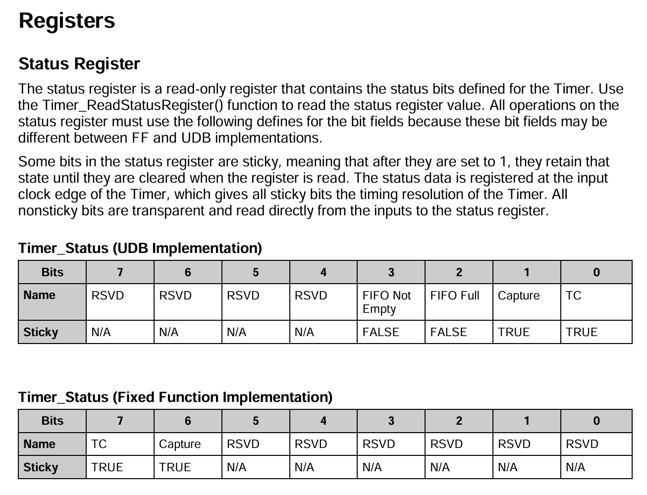
## I do not understand the instruction `overflow = 0x80 & Timer_ReadStatusRegister();`.
That is basically the point of the question :
 Therefore, `overflow` will be equal to :
- `0000 0000`if the timer period has not yet elapsed,
- `1000 0000`if the timer period has elapsed.
Everything is explained in the _datasheet_ of the _timer_ component in the sections _Application Programming Interface_ and _Registers_
## I tried to use the above instruction with an _UDB_ timer but it does not work.
Please have a look to this (from the _datasheet_) :
Therefore, `overflow` will be equal to :
- `0000 0000`if the timer period has not yet elapsed,
- `1000 0000`if the timer period has elapsed.
Everything is explained in the _datasheet_ of the _timer_ component in the sections _Application Programming Interface_ and _Registers_
## I tried to use the above instruction with an _UDB_ timer but it does not work.
Please have a look to this (from the _datasheet_) :
 ---
# Interrupts
## What is the `CY_ISR` routine and how should I configure it ?
The `CY_ISR` routine contains a bunch of instructions that should be executed when your interruption is triggered. To make it work properly, you should associate an interrupt (*ISR*) component (named "isr" for e.g.) to an component-related event in the *Top_Design* (e.g., overflow of a timer, state of a digital input pin, ect.).
On top of your code (before `main` thus), you should have something like :
```
CY_ISR (myISR){
...
// Some instructions here
}
```
and in the initialization part something like :
```
int main(void){
isr_StartEx(myISR);
...
\\ Rest of the code
}
```
*myISR* is a *Cyaddress* poiting towards the routine that should be executed when configured *isr* is triggered.
## I tried to implement an interrupt triggered by the timer but it does not work
Here are some source of errors :
- Forget to link the _Interrupt_ to the _Timer_ in the _TopDesign_,
- Forget to check _On TC_ in the _Timer_ (_TopDesign_),
- Forget to enable the _Interrupt_ in the initialization (see `startEx()`),
- Forget to call `Timer_ReadStatusRegister()`at the end of the ISR routine. Needed to reset the timer (the sticky TC bit).
---
# DAC
## I'm sending a $\sin$ signal to the *DAC* but output sound is inaudible
If the sound is bad, you might have sent the wrong signal to the DAC. We are using an 8-bit DAC. Therefore, you cannot send the $sin$ signal as such because :
- The array *signal[N]* contains *float* numbers while *DAC* expect unsigned integers (*uint8*). Floats would thus be casted to integers.
- A $\sin$signal is bounded in [-1,1] while the DAC expect a range of integers between 0 and 255. If we do not make proper conversion, we will only end with an array of 0's.
---
# Interrupts
## What is the `CY_ISR` routine and how should I configure it ?
The `CY_ISR` routine contains a bunch of instructions that should be executed when your interruption is triggered. To make it work properly, you should associate an interrupt (*ISR*) component (named "isr" for e.g.) to an component-related event in the *Top_Design* (e.g., overflow of a timer, state of a digital input pin, ect.).
On top of your code (before `main` thus), you should have something like :
```
CY_ISR (myISR){
...
// Some instructions here
}
```
and in the initialization part something like :
```
int main(void){
isr_StartEx(myISR);
...
\\ Rest of the code
}
```
*myISR* is a *Cyaddress* poiting towards the routine that should be executed when configured *isr* is triggered.
## I tried to implement an interrupt triggered by the timer but it does not work
Here are some source of errors :
- Forget to link the _Interrupt_ to the _Timer_ in the _TopDesign_,
- Forget to check _On TC_ in the _Timer_ (_TopDesign_),
- Forget to enable the _Interrupt_ in the initialization (see `startEx()`),
- Forget to call `Timer_ReadStatusRegister()`at the end of the ISR routine. Needed to reset the timer (the sticky TC bit).
---
# DAC
## I'm sending a $\sin$ signal to the *DAC* but output sound is inaudible
If the sound is bad, you might have sent the wrong signal to the DAC. We are using an 8-bit DAC. Therefore, you cannot send the $sin$ signal as such because :
- The array *signal[N]* contains *float* numbers while *DAC* expect unsigned integers (*uint8*). Floats would thus be casted to integers.
- A $\sin$signal is bounded in [-1,1] while the DAC expect a range of integers between 0 and 255. If we do not make proper conversion, we will only end with an array of 0's.
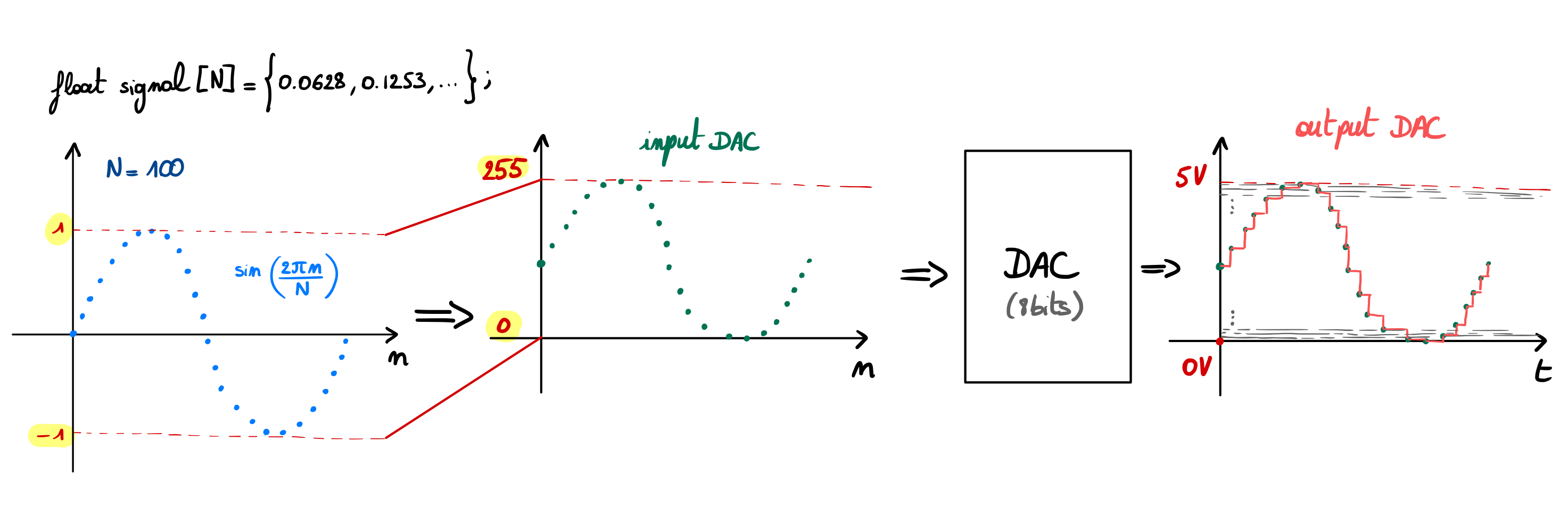 We thus need to make a linear transformation $y[n]=\alpha x[n] + \beta$ of *signal* $x[n]=\sin\left(\frac{2\pi n}{N}\right)$ to land in the range [0,255] and then *cast* in *uint8* before sending values to the DAC using `DAC_SetValue(y[n])`.\
The DAC will then convert the signal into an analog signal and send it to the right output pin.
## How the DAC knows where to send the analog output signal ?
You should give it this information in the *TopDesign*. The DAC component should be connected to an analog pin. This pin should be assigned in *.cydwr* file to the port corresponding to the audio output of your external board (using *Extension_PSOC* schemes).
We thus need to make a linear transformation $y[n]=\alpha x[n] + \beta$ of *signal* $x[n]=\sin\left(\frac{2\pi n}{N}\right)$ to land in the range [0,255] and then *cast* in *uint8* before sending values to the DAC using `DAC_SetValue(y[n])`.\
The DAC will then convert the signal into an analog signal and send it to the right output pin.
## How the DAC knows where to send the analog output signal ?
You should give it this information in the *TopDesign*. The DAC component should be connected to an analog pin. This pin should be assigned in *.cydwr* file to the port corresponding to the audio output of your external board (using *Extension_PSOC* schemes).