ER-TFT035-6, ESP32-WROOM, and SPI Connections Verification #1684
-
|
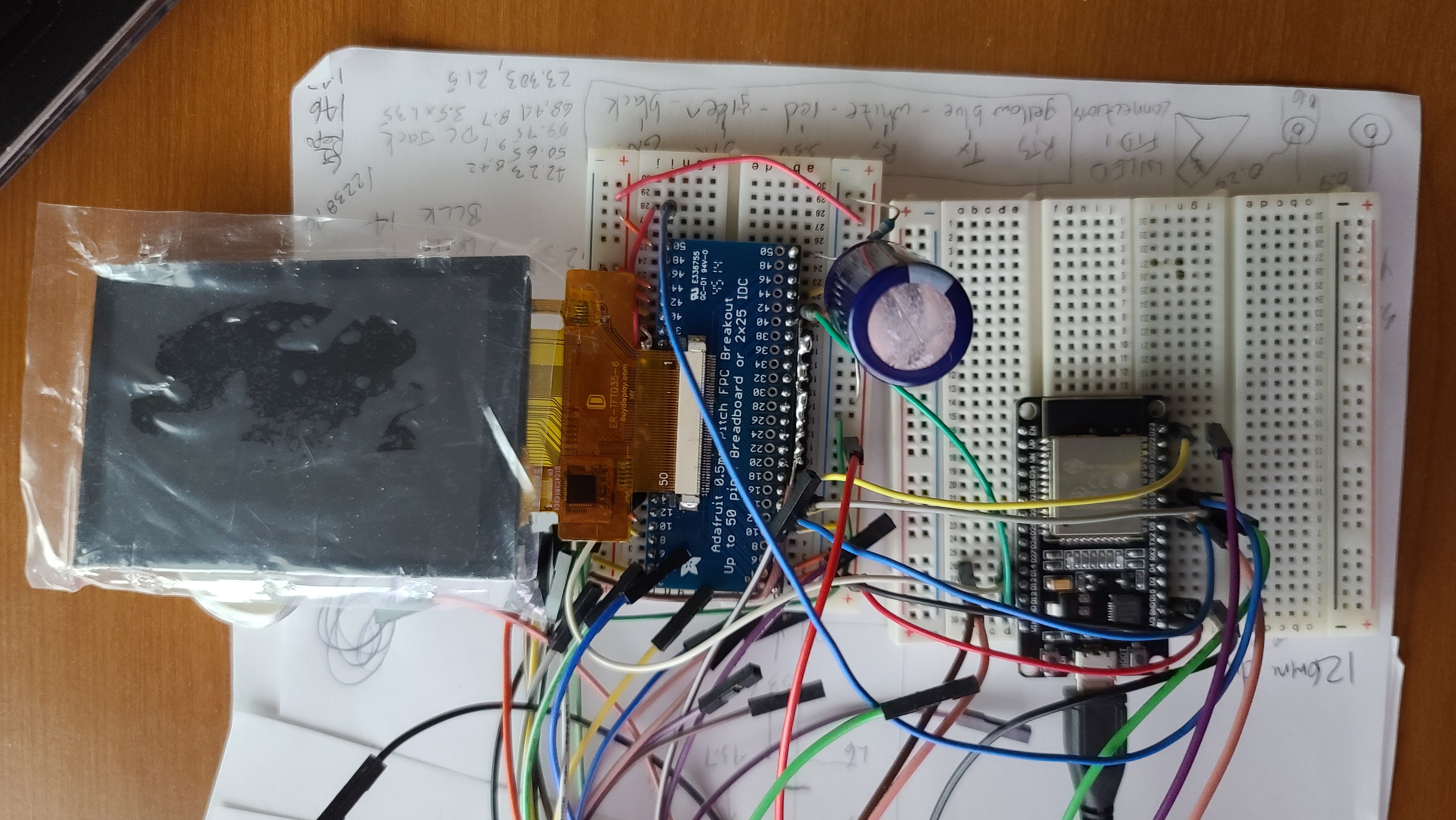
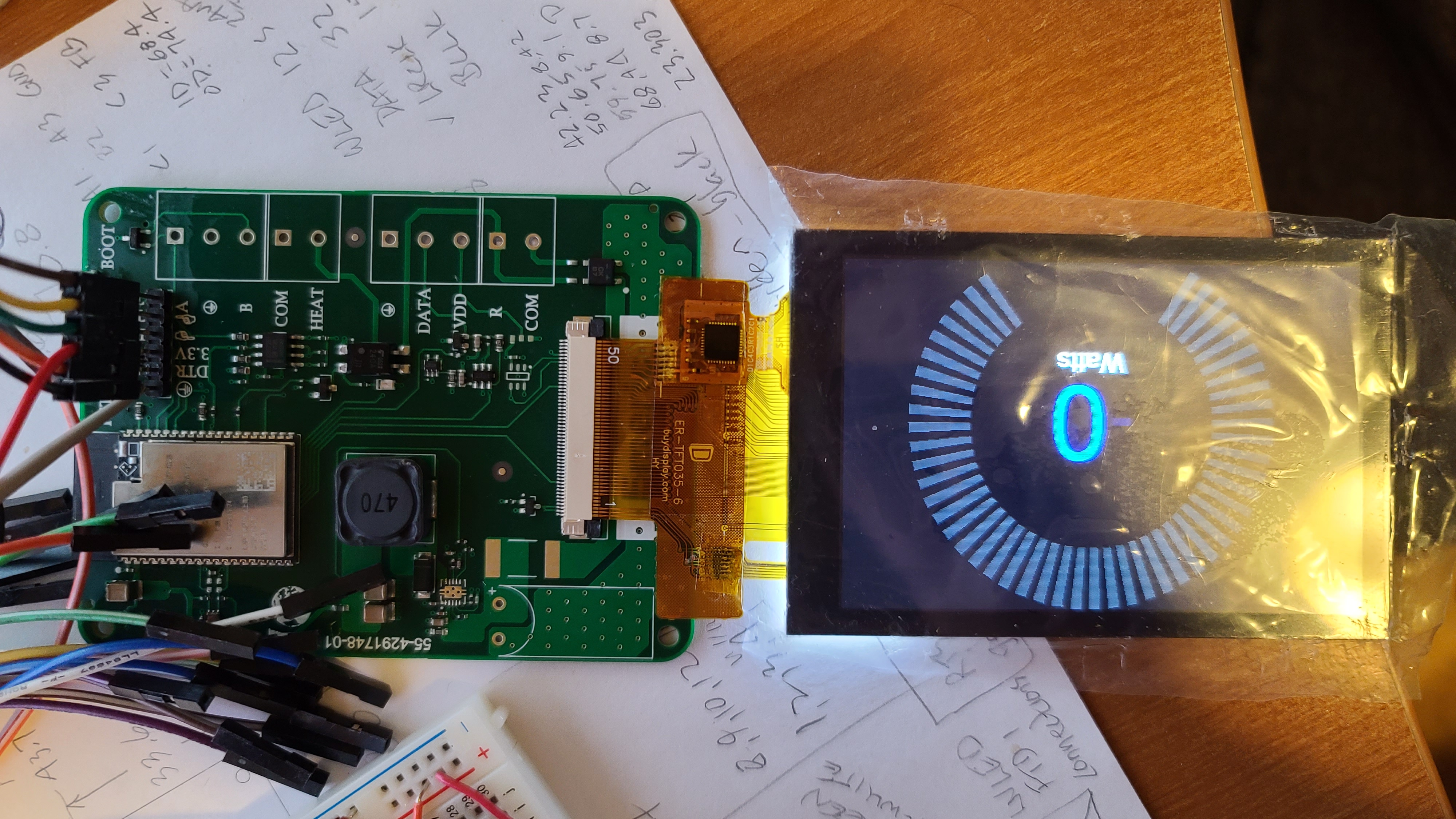
It's been a few years since I've messed with this and my current setup is not displaying anything on the screen so I'm hoping I can get my setup confirmed to rule out software issues. I ran the read_user_setup example and it returns the expected results based on my configuration: I created a setup file in the upper directory of 'TFT-eSPI_Setups When I run the I just have the panel and not the module which has the panel mounted onto a board with electronics. I'm using a FFC breakout board which I soldered up so that obviously is a potential source of the problem although I don't see any opens or shorts. I know that the screen is getting 3.3V power from my measurements and the backlight is on. I'm using the ESP32-WROOM board to power the LCD with 3.3V but I've got a 4700uF cap on the power rail and a 60Ω resistor on the LED Cathode connection to ground to limit current draw. I'd show a picture of the board connections but it's a bit of a mess and would be hard to follow. At this point I'm just hoping that someone could look over the basics and make sure I haven't overlooked something simple. |
Beta Was this translation helpful? Give feedback.
Replies: 5 comments 9 replies
-
|
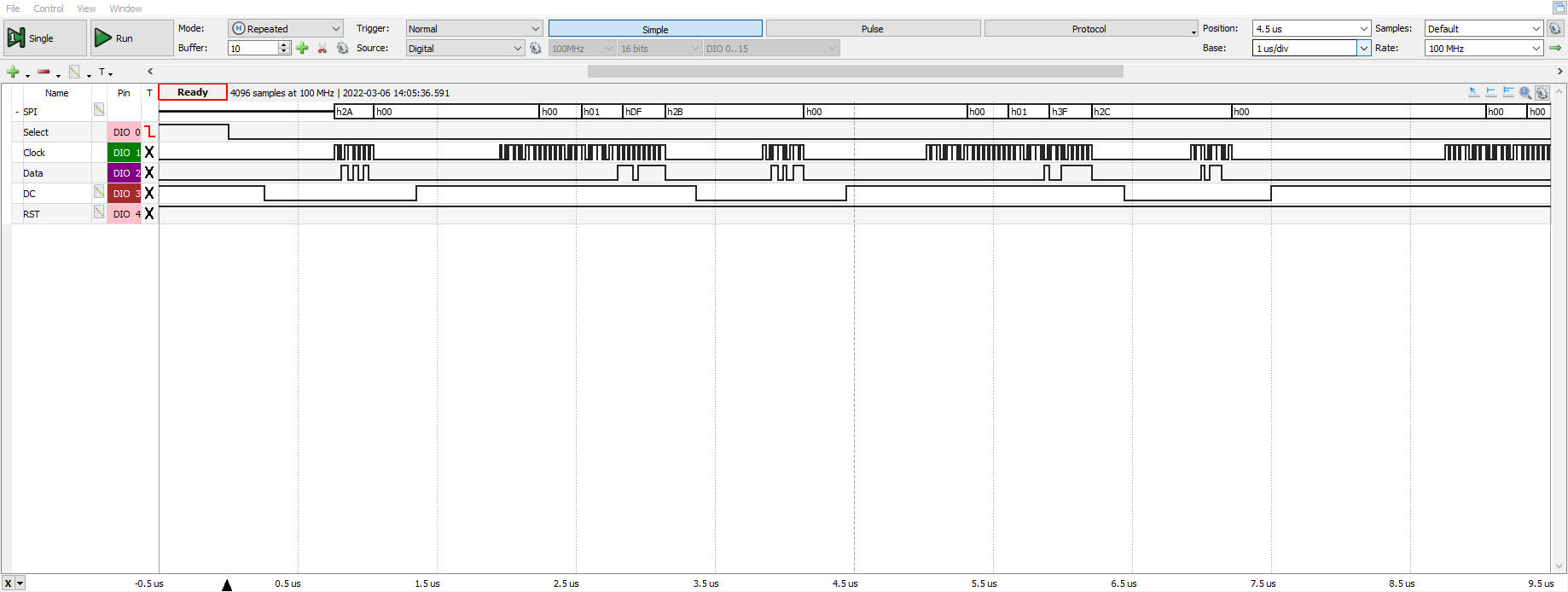
I'm hoping that someone else has taken logic analyzer captures and can confirm if this is normal. I'm just using an Analog Discovery 2 to capture the data since it was convenient but to be honest I don't always trust it 100%, especially in this case when the SPI clock is supposed to be running at 27MHz. The clock is showing at 25MHz but this is pushing the capability of the AD2 so I'm going to say it's correct. This basically looks OK so I'm leaning more towards a hardware issue on the FFC connector breakout board although I've checked soldering again. From what I've searched my configuration is correct but it would be nice to just get a quick confirmation that everything is correct.
|
Beta Was this translation helpful? Give feedback.
-
|
The logic analyser output looks OK. I can see the CASET and PASET commands, coordinates and a pixel colour being transmitted. |
Beta Was this translation helpful? Give feedback.
-
|
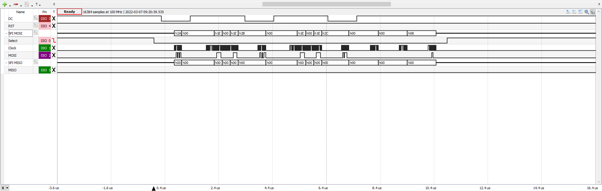
The screen I have uses the capacitive touch screen, not the resistive. I forgot about needing MISO to read the ILI9488 registers so I'll connect that and see if I can get 1 step closer. I forgot to mention that I do have the screen configured for 4-wire SPI. |
Beta Was this translation helpful? Give feedback.
-
|
The capacitance touch screen may be I2C so check as then it must be on a seperate bus. If the TFT is othe only perihperal on the SPI bus then you can connect MISO and read the CGRAM even though nothing is displayed, that would indicate if communication is occurring. |
Beta Was this translation helpful? Give feedback.
-
|
Yes, the CTP is definitely I2C, the datasheet for the screen I'm using is https://www.buydisplay.com/download/manual/ER-TFT035-6_Datasheet.pdf Yes, definitely the TFT is the only part on the SPI bus. I'm getting the breadboard setup now to connect MISO |
Beta Was this translation helpful? Give feedback.
-
|
So it looks like nothing is on MISO when running the TFT_ReadWrite_Test sketch after I connected MISO and modified my User_setup.h
I ran the Read_User_Setup sketch to confirm and it does show that MISO is defined: Since it's a new day I'll go back through all the connections and check again that I haven't missed a connection. One thing I did do yesterday was probe the ESP32 board I'm using for testing to confirm that the silk screen marking is correct and the GPIO on the ESP32-WROOM module is correctly marked on the dev kit board. I also used the Analog Discovery 2 to power the LCD but I'm not sure if that's necessary as the LDO on the ESP32 module should be able to supply 300mA easily. The hunt goes on ... |
Beta Was this translation helpful? Give feedback.
-
|
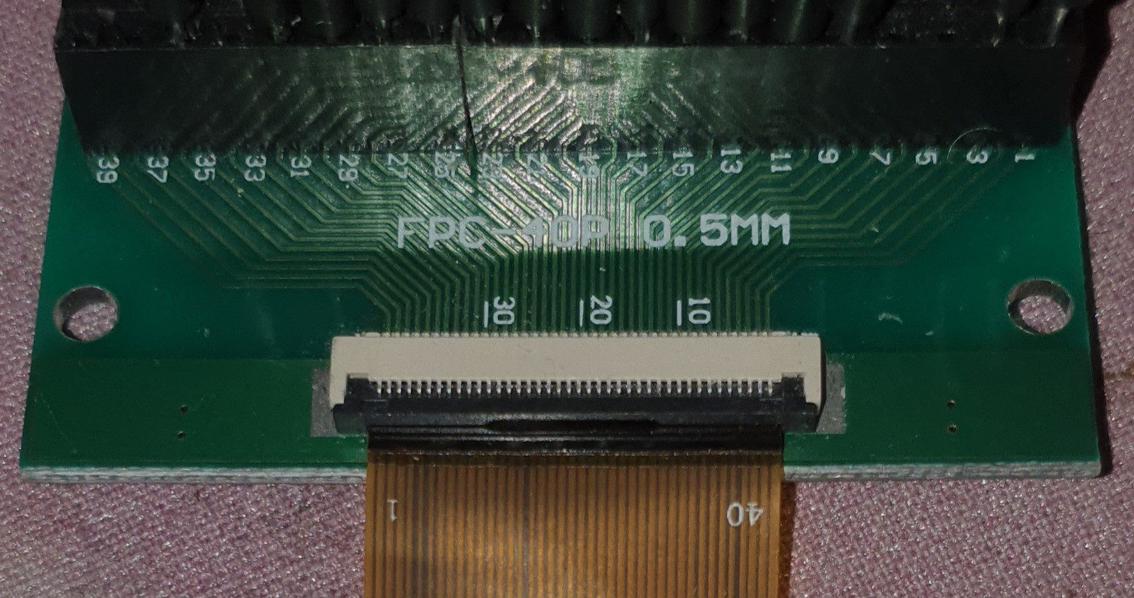
Just a thought... Check the display ribbon pin order conforms to the FPC adaper. Sometimes the pin numbers are reversed on the board compared to the ribbon numbering. The ribbon does not connect properly when put into the connector the other way around (i.e. contacts on top)!
|
Beta Was this translation helpful? Give feedback.
-
|
Good thought, that actually did get me the first day and I was hoping correcting that would solve the problem but it didn't. I do have a backup screen and tried that yesterday after making the wiring changes and it didn't work so I've switched back to the original screen for now.
|
Beta Was this translation helpful? Give feedback.
-
|
So I went through and probed from the ESP32 module pin to the top of the pin of the FFC connector for each of the control signals and I get continuity. I replaced 1 wire that seemed a little flaky but I still just get 0V on MISO during the TFT_ReadWrite_Test sketch. If I press on the FFC connector during the LA capture nothing changes so as far as I can tell the connector may be soldered OK. I even changed the LA trigger to be on a rising edge for MISO and pressing on the connector never gave me a rising edge so this sucker refuses to talk. I even pulled out my backup screen and the same thing is happening so it's not like I have a damaged screen. I have IM0-IM2 tied to VCC so that should configure the panel for |
Beta Was this translation helpful? Give feedback.
-
|
I m not sure where the problem is. Maybe see if you can get the CTP running on it's own to see if that works. On the FPC it looks like the black clamp is not latched in one one side. To be sure of the library I ran 2.4.32 with a ILI9488 in case some update has caused an issue and it ran fine. I think what I would do in this situation (after seeing if the STP works) is strip the whole setup down and start again from the data sheets. :-( |
Beta Was this translation helpful? Give feedback.
-
|
Thanks for trying that and I was hoping that maybe someone else who's worked with these could confirm my setup. It looks like my PCBs will arrive this week so that will give me a better setup to test without all the wires and breadboards which can only help. I've taken this apart a few times and even had my wife confirm pinouts with me! I haven't even tried the CTP so I guess I can hook that up and see if I can get the I2C bus talking to me. Stay tuned... |
Beta Was this translation helpful? Give feedback.
-
|
Can someone please give me the last 2 days of my life back! I got lucky and my boards were delivered early and of course first time things just worked. I had a feeling that something was up with the FFC breakout but I couldn't walk away and wait.
|
Beta Was this translation helpful? Give feedback.
-
|
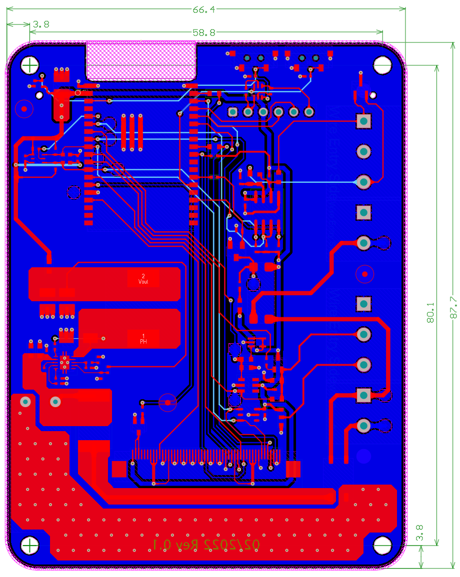
Great. Not sure if this is the case with that PCB but the tracks and ground plane on all layers should not be present in the area of the WiFi antenna otherwise the signal strength will be degraded significantly. |
Beta Was this translation helpful? Give feedback.
-
|
I actually have a PCB cut out under the WiFi antenna area of the module At some point I still want to go back to that breakout board and see what I missed but there are plenty of other things going on to keep me busy! Thanks for following up! |
Beta Was this translation helpful? Give feedback.
Can someone please give me the last 2 days of my life back! I got lucky and my boards were delivered early and of course first time things just worked. I had a feeling that something was up with the FFC breakout but I couldn't walk away and wait.