Can a Pico drive a ILI9486 16-bit parallel 3.5” display? EDIT: Success! #2300
Replies: 7 comments 7 replies
-
|
Link to Amazon page where I purchased: https://www.amazon.com/Hosyond-480X320-Display-Parallel-ILI9486/dp/B0B5MLM7VM here’s the pinout |

Beta Was this translation helpful? Give feedback.
-
|
It looks like the IMx pins are not accessible to convert the display to SPI or 8 bit parallel. So without potentially damaging surgery to the board you are stuck with 16 bit parallel. The ILI9486 has been tested in 8 bit parallel mode, so I would expect 16 bit parallel mode to work. Keep the wires short <10cm and use at least 3 GND connections to the display. This setup would be a good starting point (change driver to ILI9486_DRIVER): https://github.com/Bodmer/TFT_eSPI/blob/master/User_Setups/Setup106_RP2040_ILI9481_16bit_parallel.h |
Beta Was this translation helpful? Give feedback.
-
|
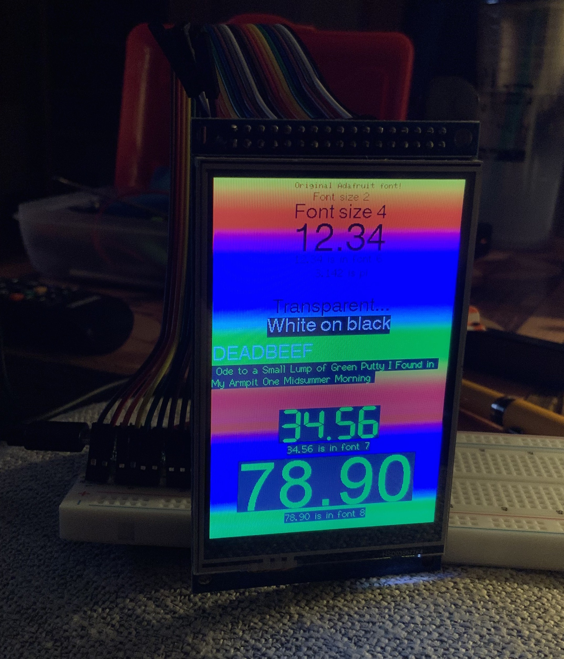
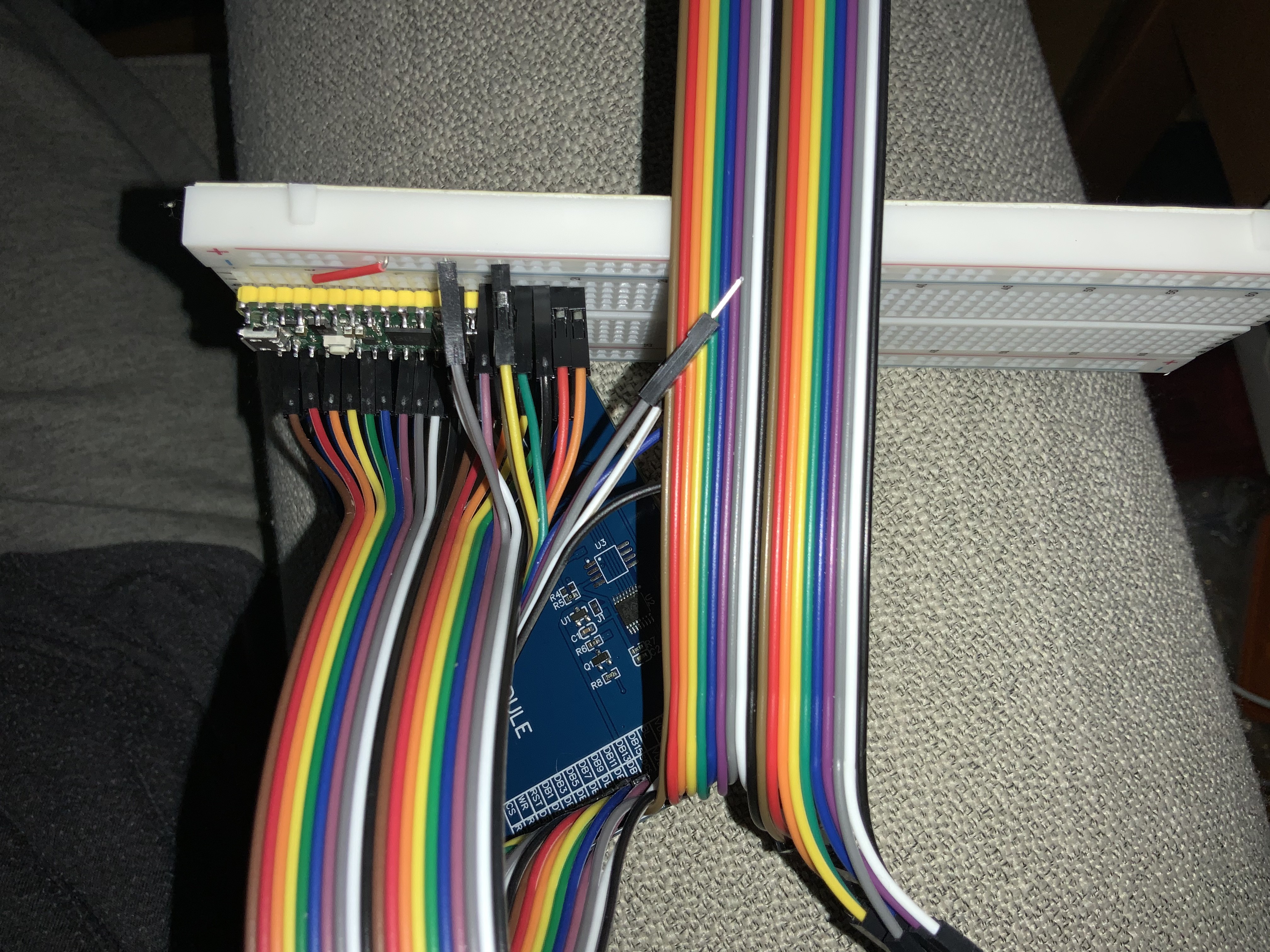
SUCCESS!! See photos below! Wow it worked on the second try! I could barely believe my eyes! (I only got a gray screen with half a rectangle at first, until I discovered the header saying RD must be connected to 3V3. That fixed it!) I was able to compile and run at least a dozen of your Example demos too as-is and they worked beautifully! Performance is great reaching 500 FPS in one of your tests, I forget which. In any tests that you listed reference performance numbers, my display was either on par or exceeded those results. I'm quite pleased. Brilliant work! Outstanding comments documenting the code. I don't even write C but was still able to manage. I had to use 3 different DuPont bundles to make it all work, and the 2 main ones are way longer than 10cm (at least double) and it still works! I was only able to use 1 or 2 GND and that didn't appear to have any impact either. Here are the results from the "graphics test one lib": 2 18:45:27.705 -> Screen fill 46247
3 18:45:27.738 -> Text 5421
4 18:45:27.772 -> Lines 54902
5 18:45:28.005 -> Horiz/Vert Lines 4078
6 18:45:28.039 -> Rectangles (outline) 2392
7 18:45:28.039 -> Rectangles (filled) 111733
8 18:45:28.173 -> Circles (filled) 19938
9 18:45:28.207 -> Circles (outline) 19710
10 18:45:28.207 -> Triangles (outline) 14914
11 18:45:28.240 -> Triangles (filled) 42192
12 18:45:28.307 -> Rounded rects (outline) 8440
13 18:45:28.307 -> Rounded rects (filled) 114897
14 18:45:28.440 -> Done!I did a DMA graphics example and there was a huge performance boost with DMA enabled in the .h file vs disabled, despite your comments warning not to enable DMA for parallel(?). Something like 500 FPS vs 350 FPS. I also tried overclocking up to 250 MHz and it had a proportionate improvement in benchmark results just as you'd expect. I didn't try adjusting the MHz rate in the header at all, I just allowed defaults. I think 200 MHz worked perfectly but 250 MHz started failing to complete drawing the bottom of the 48 little red rectangles in one of the tests, exactly as the header predicted. The bouncing colorful rotating cube was smooth as can be, visually a solid >=60 FPS just from how it appeared. The 16 bit color test is really cool, I like how it draws 8 bit colors at the end to demonstrate the difference. The rainbow spectrums are all brilliant and flawless. Are there more experiments that would be useful for you? I'm happy to test, as it sounds like I'm the first to try a 16 bit parallel on RP2040. I also got the SD card to work! It recognized the size of an old 32MB card and the size of a 128GB SDXC, but despite trying two libraries claiming exFAT and FAT12 support, none of them could read either card's contents. I'm assuming if I had a 2GB FAT32 card it would work though. Is there a way to allow the SPI SD Card interface to work while the parallel display operates? (this is currently not allowed in the library.) I tried connecting the touch screen also, which uses SPI as well, but I'm still working on that. (boy I never thought I'd use all those Pico GPIO pins but I'm squeezing every last one and still not sure if I'm 1 short!) Ideally the 16 bit parallel display would operate, and the XPT chip and SD card would both operate over SPI. I was confused though by the seller's display pinouts (posted above) having a T_CS touch screen chip select, an SDCS SD chip select, and then an F_CS "Flash chip select control pin" it says "when using the Flash extension". I used the SDCS to drive the SD card but can't figure out what this F_CS is for. Do they literally mean a camera flash? Like how Apple iPhones "flash" the screen as an improvised camera flash?
|

Beta Was this translation helpful? Give feedback.
-
|
Hello, I'm new to the development board world and am using the same display on an STM32F401 (black pill). I'm trying to get the display working but am just getting a grey colour when I try TFT_Print_Test. I commented out #define TFT_RD and connected RD on the display to 3.3V on the dev board. Would you mind sharing your User_Setup.h that you used? I should also note; I'm only trying to get the screen working and not the SD card or touch interface. |
Beta Was this translation helpful? Give feedback.
-
|
@pwd666 Aside from the RD to 3.3v you already tried, the other key for me was this comment:
Here are the relevant lines of my User_Setup.h for my Pico W board: Best of luck! |
Beta Was this translation helpful? Give feedback.
-
|
The latest library version on github allows the cycle time for writes to the display to be altered, see here: If the cycle period is not defined the default is 3 for that display. Your results indicate the display could be clocked faster so a value of 2 should work. Some comments in the sketches related to DMA and parallel interfaces are out of date as only the RP2040 is supported for DMA with a parallel interface. Flash means FLASH memory, typically these displays do not have that flash chip fitted. Using the SD card interface and touch is possible with your setup. You will need to use an independant touch library though. Maybe this one: |
Beta Was this translation helpful? Give feedback.
-
|
I have a similar display and got it working with the hints in this thread, thanks! |
Beta Was this translation helpful? Give feedback.
-
|
Hello! It is not working for me. Can someone help me? I was edit your config to 8 bit mode and connect RS to DC:
I noticed that there is no RD pin on this display, however this same display works fine with Arduino Mega 2560 and UTFT library, but for some reason I can't get it to work on RP2040. I also tried desoldering the logic level converters and soldering jumpers in their place. The result was the same, so I returned everything back.
|


Beta Was this translation helpful? Give feedback.
-
|
I connected the display in 16-bit mode, like this: Then I used a User_Setup.h like this: And some code... ...
|

Beta Was this translation helpful? Give feedback.
-
|
I just tried your setup and it doesn't work for me. However, your code example does not compile. Could you give the correct code for the purity of the experiment? I fixed your code, but I still get a white screen. |
Beta Was this translation helpful? Give feedback.
-
|
Bro, I really beg you. Please show me your archive with the project and the library with which everything works for you. Yesterday I ordered another display, 8 bit, but it also does not work. I can't figure out what the reason is. I also tried two different boards with RP2040, same result. Basically, it's a white screen and various artifacts. I really ask for your help. You are the only person who answered me. |
Beta Was this translation helpful? Give feedback.
-
|
I've put the whole project on Github now, https://github.com/bphermansson/3_5inchOledTest. Check that User_Setup.h in .pio/libdeps/pico/TFT_eSPI/ is correct after you compiled the code for the first time, I'm not sure if the library installation overwrites it. |
Beta Was this translation helpful? Give feedback.
-
|
Thank you! I try it later. |
Beta Was this translation helpful? Give feedback.
-
How did you get dma working? Whenever I try using dma or any sprites, I get distorted images like this. |

Beta Was this translation helpful? Give feedback.
Uh oh!
There was an error while loading. Please reload this page.
Uh oh!
There was an error while loading. Please reload this page.
-
Hi I’m new to this and I am wondering if my Pico can drive this “STM32 version” display:
http://www.lcdwiki.com/3.5inch_16BIT_Module_ILI9486_SKU:MRB3503 ?
It’s a 3.5” LCD from Amazon with ILI9486 intended for STM32 and appears to be 16-bit parallel only? I’m confused because the ILI9486 chip reference manual says there are 3 IM2 resistors that allow your choice of 3 pin SPI, 4 pin, 8 bit parallel, or 16 bit parallel. Is that something hard wired into the board I cannot change?
I found a cool side by side YouTube video someone did with this display in SPI vs parallel and it was dramatically better performance in parallel. But as a beginner I’d be much happier if I could switch this to SPI mode for now.
I’m just a hobbyist new to MCUs and tinkering and ordered the wrong display by mistake unaware of SPI vs parallel mode, but now it seems like an interesting challenge and I was just hoping you could advise if this is doable or not? From reading the source and user files it seems like 16 bit parallel RP2040 is in fact possible but I’d feel better if I wasn’t the first person to attempt this lol.
My ultimate goal would be to get this working in MicroPython, but I'm not opposed to C and flashing the Arduino code if that's my only choice.
I assume I won’t have enough pins to connect the touchscreen or the MicroSD card slot, correct?
I wasn’t sure if I could use a shift register chip like HC595 to turn one pin into many.
Thanks for your expertise, this is an absolutely incredible resource here!
PS: I spent about 2 hours searching and reading every issue and discussion here pertaining to parallel, Pico, RP2040, and ILI9486 before making this post. 😊
Beta Was this translation helpful? Give feedback.
All reactions