Power Supply, Flickering/Jittery Bright LEDs #190
Replies: 4 comments 5 replies
-
|
|
Beta Was this translation helpful? Give feedback.
-
|
I've been reading up on being able to connect via USB to debug while using an external supply for the LEDs. The risk appears to be in the +5 backfeeding into the USB host, and suggestions given to mitigate this were to slap a diode or disconnect the +5 from the USB cable and/or use a sacrificial USB hub between the host and module. Adafruit says for their ESP32 Feather V2:
So your image 2 with a modified cable or sacrificial hub should be ok, but it is not something I have tried. But am curious as to how others have done this and how safe it is. I've seen other best practices regarding putting a 300-500 ohm resistor on the data line closest to the strip, and everywhere you inject power into the strip use a 1000 uF 6-16v capacitor across +5v and ground to handle surges in demand (I've seen injecting power every 50 LEDs as a suggestion, but you should measure the voltage drop in conjunction with eyeballing where there is brightness drop). And there is also this hint for longer runs with multiple power supplies (connect the grounds, disconnect the +5 in the strip where you want to separate the power supplies) but other sources suggest not doing this. Perhaps we can add a Wiki or something for wiring best practices - but I'm too new to this to be able to contribute with the benefit of experience. |
Beta Was this translation helpful? Give feedback.
-
|
like this? i just made sure my voltage was same as output pin. I was a little concerned about that backfeed into usb. However, i have flashed this thing at least 100 times in the past 24 since i figured out how to power the lights and get them to work. |
Beta Was this translation helpful? Give feedback.
-
|
i still want an explanation why i can't power the chip on one power supply and the leds on another...w/ chip supplying the data to the leds only. ... something about shared Grounds??? so if i powered chip from usb, but connected a gnd port to the power supply ground it would of worked? |
Beta Was this translation helpful? Give feedback.
-
|
The data line fluctuates voltage relative to the ground on the chip. If you don't tie the ground from the chip to the ground of the strip, the strip can't detect the data line fluctuations. So PS1 has +5 to chip, ground to chip and to strip's ground. PS2 powering the LEDs has +5 and ground to respective positions on the strip. Then chip's data line gets hooked to the data of the strip. |
Beta Was this translation helpful? Give feedback.
-
Is there a common ground between, the different power supplies and other electronic? |
Beta Was this translation helpful? Give feedback.
-
|
Your second pic is correct but you have to tie the grounds together if they’re not connected internally. Do not tie the powers together, keep them separate, though if both are 5V it should be OK anyway.
… On Jan 4, 2023, at 6:22 AM, stretch911 ***@***.***> wrote:
<https://user-images.githubusercontent.com/121883463/210572533-d22b3b5b-0ab2-4773-ab9c-871e3d3bfcc6.jpg>
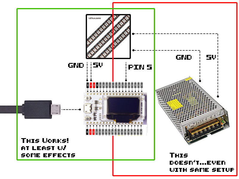
when i use USB power on HELTEC and power the LEDs (not too many) off 5V and GND provided on the HELTEC, things work (w/ exceptions w/ certain effects).
when i power the HELTEC w/ USB, and the LEDS with PowerSupply...supplying data from PIN5, the lights GO CRAZY.
<https://user-images.githubusercontent.com/121883463/210575136-8375b243-cfe1-42f1-8037-4cb124414a35.jpg>
The above configuration works great...
I can deal with this, but just want to know why using separate power supply freaks the LEDs out? I thought at first it was PIN5 being at 3V...so I logic shifted it up to 5v using PowerSupply as the reference...still no go.
—
Reply to this email directly, view it on GitHub <#190 (comment)>, or unsubscribe <https://github.com/notifications/unsubscribe-auth/AA4HCF5FX2ETO7WRZIDR3RTWQWBSBANCNFSM6AAAAAATQGP5AQ>.
You are receiving this because you are subscribed to this thread.
|
Beta Was this translation helpful? Give feedback.
-
|
You can power them separately. I do it all the time with two different power supplies when dealing with 12V strips and 5V chips, for example. The only catch is your power must NOT be combined but your grounds MUST ALWAYS be combined. That’s it, that’s all, works great, less filling, etc.
So yes, common ground between the board and the strip. Otherwise the signal that you send from the chip has no ground reference relative to the strip.
Note that if you’re using a 3.3V signal, you technically need a level converter to 5V, but it has always worked for me at 3.3 with the ESP32. I think the threshold is only 2V for the signal.
* Dave
From: rodney-dfwsurgical ***@***.***>
Sent: Wednesday, January 11, 2023 9:06 AM
To: PlummersSoftwareLLC/NightDriverStrip ***@***.***>
Cc: David W Plummer ***@***.***>; Comment ***@***.***>
Subject: Re: [PlummersSoftwareLLC/NightDriverStrip] Power Supply, Flickering/Jittery Bright LEDs (Discussion #190)
i still want an explanation why i can't power the chip on one power supply and the leds on another...w/ chip supplying the data to the leds only. ... something about shared Grounds??? so if i powered chip from usb, but connected a gnd port to the power supply ground it would of worked?
Is there a common ground between, the different power supplies and other electronic?
—
Reply to this email directly, view it on GitHub <#190 (reply in thread)> , or unsubscribe <https://github.com/notifications/unsubscribe-auth/AA4HCFYNEO7E7RXULLBV47LWR3R7XANCNFSM6AAAAAATQGP5AQ> .
You are receiving this because you commented. <https://github.com/notifications/beacon/AA4HCF5YJKDWZFLYOUIJ6FTWR3R7XA5CNFSM6AAAAAATQGP5ASWGG33NNVSW45C7OR4XAZNRIRUXGY3VONZWS33OINXW23LFNZ2KUY3PNVWWK3TUL5UWJTQAI4LFO.gif> Message ID: ***@***.*** ***@***.***> >
|
Beta Was this translation helpful? Give feedback.
-
|
thank you. that's really the core of why i was asking, cause some of this chips have regulators or prefer 3.3v but the lights use 5. i've done a TON of research and it seems the data signal just has to change by 2v within a certain range. if your data line is to far from the chip you need a logic shifter OR a sacrificial LED that boosts the signal ;). I've learned the hard way too...2 meters of fried LEDS, 2 dev boards and a power regulator on a power supply module by applying too much voltage....and everything on that rail ....sheeze. oh what fun! |
Beta Was this translation helpful? Give feedback.
Uh oh!
There was an error while loading. Please reload this page.
-
one more issue I'm dealing with is w/ Power Supply.
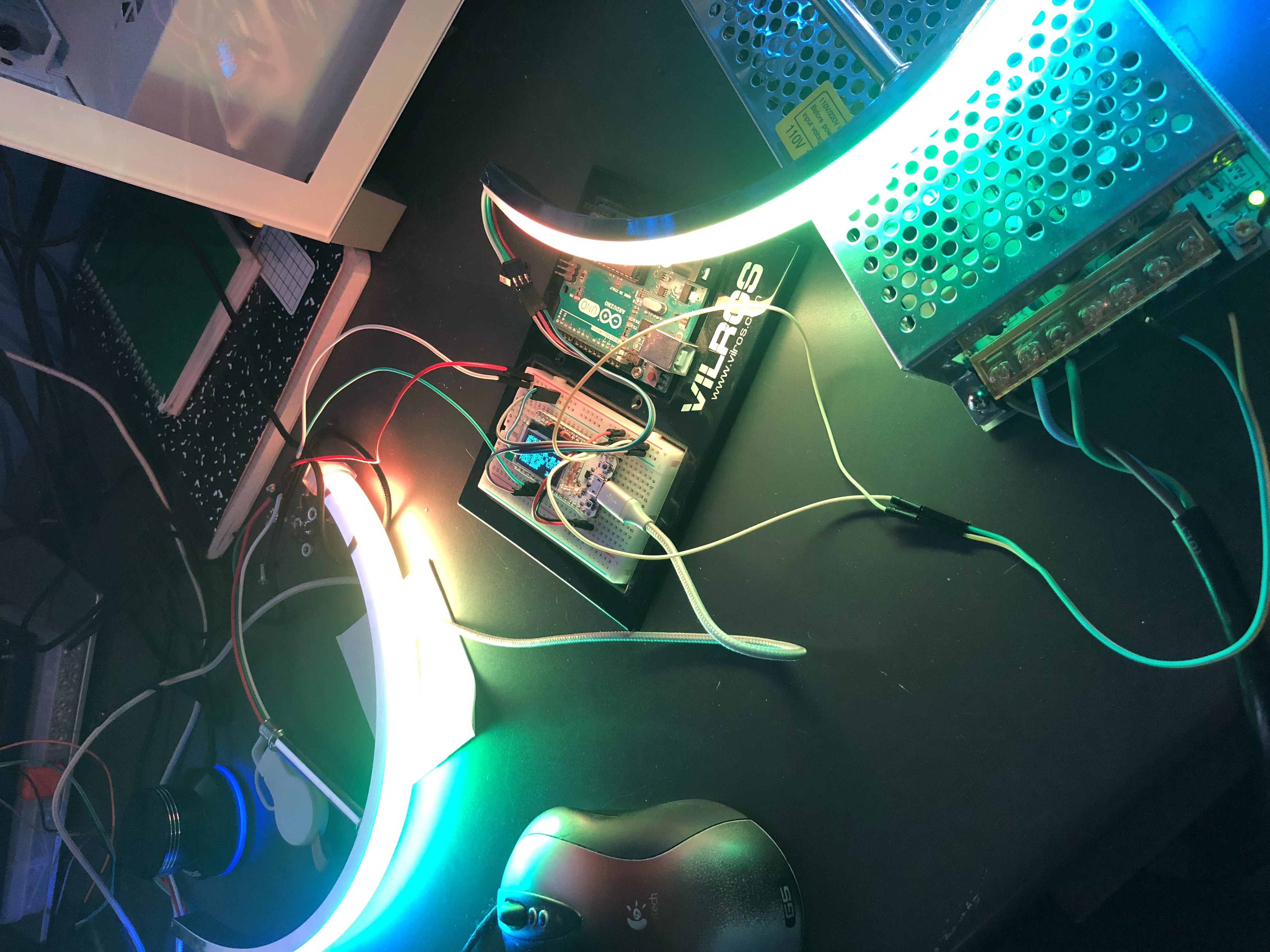
I am testing which effects work w/ Heltec and noticed that say for instance new ColorFillEffect(CRGB::White, 1) would light the LEDS, then heltec would crash. This was using USB power and tapping a single 42 pixel led strip into 5, 5V and GND. What I surmised was the LEDS were pulling too much current and heltec said NO WAY. I guess it got starved? I decided to try my 5V power supply rated at 30a, purchased from BTF. I kept the Heltec plugged into USB (due to so many compile/uploads as I test). I left the Data on PIN5 and moved the LED power and ground to the 5v 30a PSM. The lights went nuts...very bright w/ hints of rainbow flickering on the pixels. I thought...ok, Heltec is probably putting out 3V on PIN5 for data and this just wasnt enough..so, used a logic level switcher on pin 5 referencing up to power supplied 5v rail and ground. This didn't help either....I don't understand.
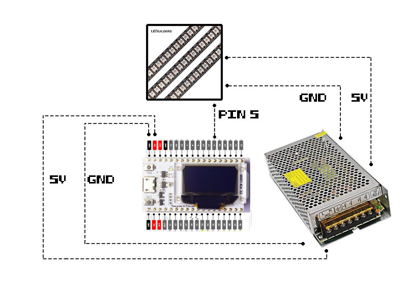
Here is what is working...i'm using the 5v psm to power a breadboard + and - rail. I then use that to power the heltec as well as the LEDs. The only thing the leds are using now is PIN5. Now everything is working, even brighter I might add...
I don't have oscilloscope however voltage matches USB power at 4.89. Can someone give some reasons? thanks in advance.
Beta Was this translation helpful? Give feedback.
All reactions