STL Slicing and Printing Q&A #42
Unanswered
StephenCarlson
asked this question in
Q&A
Replies: 0 comments
Sign up for free
to join this conversation on GitHub.
Already have an account?
Sign in to comment
Uh oh!
There was an error while loading. Please reload this page.
Uh oh!
There was an error while loading. Please reload this page.
-
Perhaps the hardest "Great Filter" in building a MiniHawk-VTOL is the 3D printing process of the project parts. The first hurdle that one faces in this quest is the actual slicing of the part files, and perhaps even just understanding which files do what and how many are printed. I've added the Parts Tree to the Readme document in an attempt to articulate all the variations and versions of each part for building a full MiniHawk. For the rest of this post, I'll focus on the Left Nacelle and Left Motor Tilt Mount as the example.
Below is an excerpt of the Parts Tree for the Nacelle and Tilt Mount:
What this branch represents is that each Left Nacelle (the arm that sticks out of the wing and holds the tilting motor/rotor) can be either a Ball-Bearing version of the design, or a Non-Ball-Bearing version. For whatever version you want to print (I recommend the Non-Ball-Bearing for your first build), the associated files are specified as leafs in the tree; so, if we want to make a Non-Ball-Bearing Nacelle, I would use the
MH7_Nacelle_B-NoBearing.stlandMH7_Nacelle_B-NoBearing.stlSTL files. The Motor Tilt Mount (the cup that holds the tilting motor) should be selected to correspond to the bearing choice, so here, we want to print theMH7_TiltMount_A-NoBearing.stlfile. The Motor Tilt Mount has two pieces, with the_Apiece being the forward piece, and a_Bpiece that gets glued on the back, with this_Bpiece being exactly the same for either the Ball-Bearing or Non-Ball-Bearing versions. The motor itself and the type of metal hardware that bolts the assembly together are also noted in the tree. Remember that this is all just for the Left Nacelle, and there is a note at the bottom of the Parts Tree that explains that to generate the Right-side of anything, you simply mirror the part in you slicer software.I recognize that this is a very complicated set of steps and instructions, with scattered directives and notes, and I'm constantly trying to find time to rewrite it all. But there is a shortcut which you can use to skip all of this! On the main page of the repo, check out the
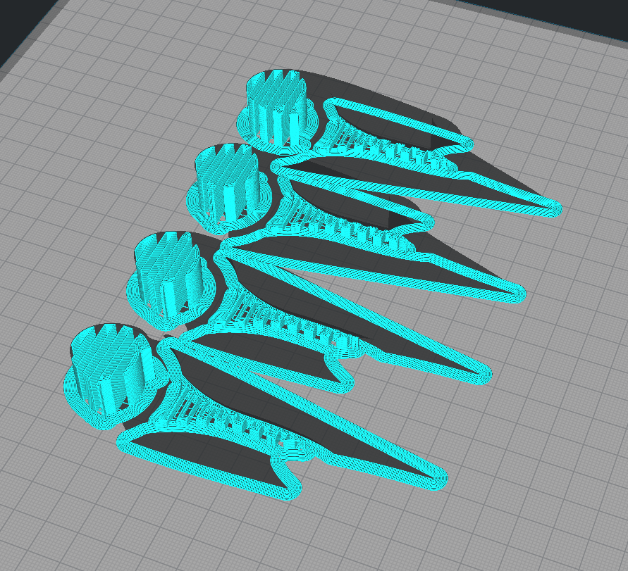
3mf-Implementationsfolder. This is where I upload all the production files that my slicing software (Ultimaker Cura) generates. For the Left Nacelle example in this post, download MH7_Nacelle-NoBearing_Set.3mf and try loading it in your slicer software. If it opens the file correctly, you should see something like this:What you are seeing is all the Nacelle pieces, for both the left and right nacelles, properly positioned on the build plate, such that you can print them all at once. The 3MF file format is the 3D printing industries' attempt to overcome the deficiencies of the ancient STL format. The file should communicate to your slicer software all the settings for slicing the parts and placement on the buildplate. If it does this correctly, this is what the Supports-Only view of the Nacelles Set should look like:
Unfortunately, despite the industry intent, the 3MF file format does not appear to consistently translate to other slicer programs. Even though these 3MF files are saved using Cura, there are sporadic reports of settings or models not translating over to other instances of Cura. Hence, the MiniHawk-VTOL project is primarily offered as the collection of STLs, with the 3MF implementation files offered where they (hopefully) work.
So, if you cannot get the 3MF files to open, you will have to manually apply the suggested slicer settings. If you look at the table on the Readme document, here are the columns that you will want to refer to:
Each row should have an equivalent match in your slicer software, or improvise as necessary. Continuing with our Nacelle Set in Cura, here is what these settings look like:
(Note the inconsistency between the table and the screenshot of 10% and 20% for infill density. Both values should be fine, use 20% if you want a really strong nacelle arm.)
I hope that the fields in the suggested print settings table are self-explanatory and easily interpreted. The only ambiguity that needs extra attention is how the Infill_Line_Directions relate to the part. What this corresponds to is how the infill geometry aligns with the part. For our Nacelle Set example, here is a screenshot of the Infill Line Direction at 20 degrees:
See how the infill is skewed by 20 degrees? We don't want to print the set like this, since the infill isn't aligned with the parts and thus will 1) Look weird being asymmetric and all, and 2) Not provide the best structural support. We want the infill to be nicely aligned to the parts such that the internal infill structures provide the best strength and symmetry. In this case, setting the infill line direction to zero looks like this:
Notice how the infill matches between parts? By setting the infill direction to an orthogonal mode, we can have nice symmetric parts! Now, it is really up to you if you want to explore other settings; infill direction loosely determine how stress is conducted through the internal structures of the part, but the skin of the part also plays a major roll. We could choose 90, 180, or 270 degrees, but be aware of how the entire set of parts inherits the pattern. Below is the 0-degrees case with all the layers shown:
For this example, I've used the Nacelles, which have an obvious flat side/split which should be flush on the buildplate. I hope that part placement and alignment is fairly easy to infer from each of the STLs in the project: If in doubt, put the flat side down! Remember that 3D-printed parts tend to be strongest in the XY (layer plane) direction, with the Z (layer stack) direction being somewhat weaker. The MiniHawk-VTOL tries to utilize the XY structural bonus where possible, but the default priority in how the airframe parts are sectioned is to print with minimal overhangs and without supports. The Nacelles override this priority since they have important structural responsibilities, and thus are the only part which requires Supports->Enabled when sliced.
As to actually printing the parts, here, I cannot help you! It is up to you to know the material that you are using, its temperature range, how the print cooling fans work on your printer and if you want to have print cooling fans blowing or not, and a myriad of other knobs and buttons that require attention.
I hope this helps. Feel free to post below for any additional clarification.
Beta Was this translation helpful? Give feedback.
All reactions