The following document serves as a comprehensive and in-depth documentation of all aspects of the software code. The purpose of this document is to inform outsiders to the Jetson Multimidia API and Libargus environment about the high-level and low-level details of our implementation. For further reading, check out the API Documentation, the Nvidia Developer Forums, and the sample applications bundled with the API.
Disclaimer: The developers of this package are themselves new to GPU programming and the Jetson environment as a whole. In the following documentation, any assumptions, or otherwise hand-wavey explanations will be stated as such.
The code for this package has been adapted from the syncSensor sample program. Due credit to Nvidia Corporation for their work.
- main.cpp
- convert.cu
- 1. float convert (CUsurfObject, CUsurfObject, unsigned int, unsigned int, uint8_t*)
- 2. float run_smem_atomics (CUsurfObject, CUsurfObject, unsigned int, unsigned int, uint8_t*)
- 3. void convert_kernel(CUsurfObject, CUsurfObject, unsigned int, unsigned int, uint8_t*)
- 4. uint8_t clamp(float val, float mn, float mx)
- CMakeLists.txt
- csignal:
TODO: Delete - ros/ros.h: Imports ROS node setup functions.
- sensor_msgs/Image.h: Imports ROS image message type. Documentation.
- sensor_msgs/image_encodings.h: Imports ending types supported by ROS images.
- sensor_msgs/fill_image.h: Imports function that creates a ROS Image message from inputted data.
- Argus/Argus.h: Imports Jetson Libargus API headers.
- cuda.h: Imports headers from the CUDA toolkit
TODO: Delete since convert.h imports it anyway? - cudaEGL.h: Imports headers for CUDA EGL streams.
- ArgusHelpers.h, CUDAHelpers.h, EGLGlobal.h, Error.h, Thread.h: See CMakeLists.txt
- convert.h: Imports CUDA color conversion kernel function.
- static const uint32_t FRAMERATE: Rate / second at which the cameras produce frames.
- static const Size2D<uint32_t> STREAM_SIZE: Resolution (width, height) in pixels of the frames.
- ros::Publisher left_image_pub: ROS Publisher object to release left camera frames to rostopic.
- ros::Publisher right_image_pub: ROS Publisher object to release right camera frames to rostopic.
- uint8_t* oBuffer: Host memory buffer used to store raw image data. 3 channels, BGR, each with width * height bytes of data.
- EGLDisplayHolder g_display:
TODO: EGLDisplay is used for rendering and is a required parameter of some of our functions, however a better understanding is necessary
This file contains almost all the code for our vc_stereo_ros2 ROS node. It define multiple functionalities include ROS setup, initiating camera session, defining capture session settings such as framerate and image resolution, acquiring frames, calling color conversion kernel, and publishing converted frames to their respective ROS topics. These actions are described in detail in the method descriptions below.
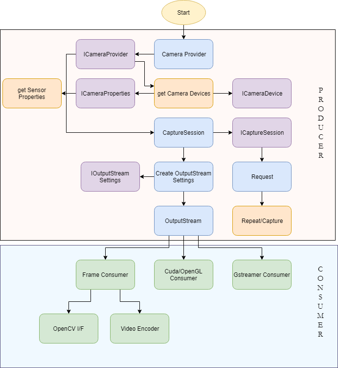
The entire program is divided into a Producer-Consumer setup The Host device acts as a Producer - initializing the capture sessions, setting up image streams, etc. The consumer is initialized with these streams and receive frames from the same. It is here where all the image processing occurs. In our usecase we specify CUDA to be the consumer as it allows us to exploit the parallelized nature of GPUs to speed up colorspace conversion, while simultaneously reducing CPU load. The consumer subsequently publishes the images to their respective ROS topics.
Simple program entry main method that is executed automatically when the program is run. Initializes the ROS nodes, sets up ROS publishers and executes the Consumer-Producer setup.
- int argc: Program argument count. C++ syntax. Unused.
- char* argv: Program argument vector. C++ syntax. Unused.
- int: Integer value representing whether or not the node closed cleanly.
This function represents the Producer side of our system. The Libargus camera pipeline is set up here (identical to the block diagram in the above image) and the CUDA consumer is initialized with the output EGL streams. This function contains a lot of dense code that would be difficult to document in comments. As such we provide an extensive line-by-line description here.
Before we start going through the code, must describe two functions from the Error.h header file - namely ORIGINATE_ERROR(char*) which is essentialy equivalent to raising or throwing an exception, and PROPAGATE_ERROR(bool) which checks whether the argument condition is true, or else passes the raised exception upwards in the program.
PROPAGATE_ERROR(g_display.initialize());
Initializes the EGLDisplayHolder object. EGLDisplay is a class that is used in rendering stream data. We are not perfectly clear on its purpose here, but know it to be necessary as a parameter to some of the other functions we utiize. This description will soon be updated.
UniqueObj<CameraProvider> cameraProvider(CameraProvider::create());
ICameraProvider *iCameraProvider = interface_cast<ICameraProvider>(cameraProvider);
The CameraProvider object along with the its interface (ICameraProvider) can be seen as the master pipeline definition.
std::vector<CameraDevice*> cameraDevices;
iCameraProvider->getCameraDevices(&cameraDevices);
if (cameraDevices.size() < 2) {
  ORIGINATE_ERROR("Must have at least 2 sensors available");
}

std::vector <CameraDevice*> lrCameras;
lrCameras.push_back(cameraDevices[0]);
lrCameras.push_back(cameraDevices[1]);
The CameraProvider creates CameraDevice objects for each detected device. Stereo synchronization requires at least two sensors. Otherwise an error is thrown. The first two detected cameras are selected as the left and right cameras.
Since sensors are likely ordered by their port number, it is important to make sure that the cameras are given the correct left / right designations.
UniqueObj<CaptureSession> captureSession(iCameraProvider->createCaptureSession(lrCameras));
ICaptureSession *iCaptureSession = interface_cast<ICaptureSession>(captureSession);
The CaptureSession object and its ICaptureSession interface, as the name suggests are the controllers of our system, that set up cameras to acquire frames. Using two sensors in the same CaptureSession is key to the keeping frame acquisition between cameras in synchrony.
UniqueObj<OutputStreamSettings> streamSettings(
    iCaptureSession->createOutputStreamSettings(STREAM_TYPE_EGL));
IOutputStreamSettings *iStreamSettings =
    interface_cast<IOutputStreamSettings>(streamSettings);
IEGLOutputStreamSettings *iEGLStreamSettings =
    interface_cast<IEGLOutputStreamSettings>(streamSettings);
if (!iStreamSettings || !iEGLStreamSettings) {
  ORIGINATE_ERROR("Failed to create OutputStreamSettings");
}
iEGLStreamSettings->setPixelFormat(PIXEL_FMT_YCbCr_420_888);
iEGLStreamSettings->setResolution(STREAM_SIZE);
iEGLStreamSettings->setEGLDisplay(g_display.get());
iEGLStreamSettings->setMode(EGL_STREAM_MODE_MAILBOX);
Exposing the StreamSettings interface of the CaptureSession. At the time of writing this, Libargus only supports the PIXEL_FMT_YCbCr_420_888 and selectively supports PIXEL_FMT_RAW16 for certain configurations (Multiple camera capture sessions are NOT supported for now). The stream can also be set between a Mailbox mode where only the newest frame is made available to the consumer, or a FIFO mode where every producer frame is made available to the consumer through the use of a fifo queue for the frames. Testing is necessary to determine which mode is ideal for individual usecases.
For further reading on stream settings, please refer to the official documentation.
PRODUCER_PRINT("Creating left stream.\n");
iStreamSettings->setCameraDevice(lrCameras[0]);
UniqueObj<OutputStream> streamLeft(iCaptureSession->createOutputStream(streamSettings.get()));
IEGLOutputStream *iStreamLeft = interface_cast<IEGLOutputStream>(streamLeft);
if (!iStreamLeft) {
  ORIGINATE_ERROR("Failed to create left stream");
}

PRODUCER_PRINT("Creating right stream.\n");
iStreamSettings->setCameraDevice(lrCameras[1]);
UniqueObj<OutputStream> streamRight(iCaptureSession->createOutputStream(streamSettings.get()));
IEGLOutputStream *iStreamRight = interface_cast<IEGLOutputStream>(streamRight);
if (!iStreamRight) {
  ORIGINATE_ERROR("Failed to create right stream");
}
Initializing the output streams for each camera by setting each camera device to the stream settings individually. PRODUCER_PRINT() and CONSUMER_PRINT() are simply wrappers around printf() that append "Producer: " and "Consumer: " respectively to the output string. This is used to determine whether a console message comes from the Producer or Consumer.
UniqueObj<Request> request(iCaptureSession->createRequest());
IRequest *iRequest = interface_cast<IRequest>(request);
if (!iRequest) {
  ORIGINATE_ERROR("Failed to create Request");
}

iRequest->enableOutputStream(streamLeft.get());
iRequest->enableOutputStream(streamRight.get());
Request object and its IRequest interface are used to acquire frames from the streams registered on the capture session. The IRequest interface object also enables the streams to start passing frames.
ISourceSettings *iSourceSettings = interface_cast<ISourceSettings>(request);
if (!iSourceSettings) {
  ORIGINATE_ERROR("Failed to get source settings request interface");
}
iSourceSettings->setFrameDurationRange(Range<uint64_t>(1e9 / FRAMERATE));
Exposes the interface to manipulate capture settings which allows us to explicitly set parameters such as framerate, exposure time, gain values, etc.
PRODUCER_PRINT("Launching disparity checking consumer\n");
StereoConsumer disparityConsumer(iStreamLeft, iStreamRight);
PROPAGATE_ERROR(disparityConsumer.initialize());
PROPAGATE_ERROR(disparityConsumer.waitRunning());
Defining and initializing the consumer object with the output streams from the cameras.
PRODUCER_PRINT("Starting repeat capture requests.\n");
if (iCaptureSession->repeat(request.get()) != STATUS_OK) {
  ORIGINATE_ERROR("Failed to start repeat capture request for preview");
}
Repeatedly make requests to the cameras for new image frames.
ros::spin();
Essesntially serves as a sleep command that pauses computation down the current thread until the program receives a terminate command. This ensures that the node does not terminate prematurely.
iCaptureSession->stopRepeat();
iCaptureSession->waitForIdle();

PRODUCER_PRINT("Captures complete, disconnecting producer.\n");
iStreamLeft->disconnect();
iStreamRight->disconnect();

PROPAGATE_ERROR(disparityConsumer.shutdown());
cameraProvider.reset();
PROPAGATE_ERROR(g_display.cleanup());

PRODUCER_PRINT("Done -- exiting.\n");
ros::shutdown();

return true;
These lines get executed once the node is terminated, to cleanup all our created objects and streams.
- None
- bool: Returns whether the process terminated cleanly or not.
This class serves as the Consumer in our Producer-Consumer system. It inherits from the Thread class which adds functionality to parallize code execution between objects. This is necessary as both camera consmers are required to acquire and operate on frames from the streams synchronously.
The public constructor for this class requires the two output streams (one from each camera) as parameters, and initializes the following attributes:
- IEGLOutputStream* m_leftStream: Stores a reference to the left camera output stream passed as an argument to the constructor.
- IEGLOutputStream* m_rightStream: Stores a reference to the right camera output stream passed as an argument to the constructor.
- CUeglStreamConnection m_cuStreamLeft: Object that connects the left camera stream to the CUDA consumer.
- CUeglStreamConnection m_cuStreamRight: Object that connects the right camera stream to the CUDA consumer.
- CUcontext m_cudaContext: CUDA context object. Used to initialize CUDA toolkit for the current program.
This method intitializes the CUDA toolkit for use within the thread through the initCUDA() method, and further connects the camera output streams to the CUDA consumers through the cuEGLStreamConsumerConnect() method.
- bool: Returns whether the thread was initialized successfully or not.
The method is responsible for receiving frames from the output streams, having them processed and converted to the appropriate colorspace and data format, and finally having the frames published onto ROS topics as sensor_msgs::Image messages. This entire process occurs inside a infinte while loop such that we can keep processing frames continuously, and as soon as they are received.
It is important to keep in mind that each iteration of the loop must take time less than (1 / Framerate) seconds. If not, we could miss certain frame pairs (In the mailbox stream mode), or throttle our actual output FPS (in the FIFO stream mode).
A description of some of the key lines of code follows:
CONSUMER_PRINT("Waiting for Argus producer to connect to left stream.\n");
m_leftStream->waitUntilConnected();

CONSUMER_PRINT("Waiting for Argus producer to connect to right stream.\n");
m_rightStream->waitUntilConnected();
The thread sleeps to delay processing until both output streams have been connected, and the consumer can start receiving frames.
if (!eglQueryStreamKHR(m_leftStream->getEGLDisplay(), m_leftStream->getEGLStream(),
    EGL_STREAM_STATE_KHR, &streamState) || (streamState == EGL_STREAM_STATE_DISCONNECTED_KHR)) {
    CONSUMER_PRINT("left : EGL_STREAM_STATE_DISCONNECTED_KHR received\n");
    break;
}

if (!eglQueryStreamKHR(m_rightStream->getEGLDisplay(), m_rightStream->getEGLStream(),
    EGL_STREAM_STATE_KHR, &streamState) || (streamState == EGL_STREAM_STATE_DISCONNECTED_KHR)) {
    CONSUMER_PRINT("right : EGL_STREAM_STATE_DISCONNECTED_KHR received\n");
    break;
}
Before each iteration of the loop, we must test the state of the streams i.e. whether they are still connected. The eglQueryStreamKHR() method determines the stream state. If the method returns false - in the case that the stream has closed down prematurely, or if the stream state shows it to be disconnected, we break out of the loop to shutdown the thread and node.
TODO: Add ros::shutdown() to thread shutdown method in case stream goes down and we must shut the node down.
CudaFrameAcquire left(m_cuStreamLeft);
CudaFrameAcquire right(m_cuStreamRight);

PROPAGATE_ERROR(left.publish(true) && right.publish(false));
We create objects of the CUDAFrameAcquire class for each of the streams. These objects hold the frames produced, offer functionality to call the colorspace conversion CUDA kernel on them, and finally publish them onto ROS topics. TODO: It might be possible to accomplish this without creating objects, which would likely help in runtime.
- bool: Returns whether the thread execution proceeded without errors or not.
This method cleans up the thread by disconnecting the output streams from the CUDA consumers through the cuEGLStreamConsumerDisconnect() method, and deinitialiing the CUDA context through the cleanupCUDA().
- bool: Returns whether the thread was closed cleanly or not.
{TODO}

- stdio.h:
TODO: Probably unneeded? Use C++ iostream instead? - convert.h (Indirectly cuda.h): Imports headers from the CUDA toolkit.
In the current version of ROS, sensor_msgs::Image does not support the YCbCr 4:2:0 image encoding format that we receive frames in from the CUDA streams. Additionally, the raw data is stored in two separate CUDA arrays in the CU_EGL_COLOR_FORMAT_YUV420_SEMIPLANAR (aka NV21) format.
From the CUDA toolkit documentation here:
Y, UV in two surfaces (UV as one surface) with VU byte ordering, width, height ratio same as YUV420Planar. (U/V width = 1/2 Y width, U/V height = 1/2 Y height.)

TODO: We aren't completely clear on the differences between YUV and YCbCr - except the former represents an analog signal, and the latter represents a digital signal. The two terms seem to be used interchangebly in most circumstances - As such we assume them to be the same.
This necessitates a colorspace conversion from the YCbCr 4:2:0 format to an encoding type supported by ROS. For our purposes we use the common BGR8 format where every pixel is defined by 3 contiguous bytes of data representing the Blue [B], Green [G], and Red [R] color channels. To accomplish this conversion efficiently on high resolution color images comprising multiple Megabytes (Million bytes) of data, while still maintaining a clean framerate output, we exploit the highly parallelized nature of the on-board GPUs of the Jetson computers.
To put this into perspective, a 4K image with a resolution of 3840x2160 in our YCbCr format where each pixel is represented by 12 bits (after averaging), every frame consists of 12.4416 Megabytes of data. For a 60 FPS throughput, we must thus process about 25 Megabytes of data every 1/60 seconds = 16 ms.
On a high level the GPU program in this file (Called a CUDA kernel) receives frames from the CUDA streams, breaks them down into smaller blocks, operates on each block in parallel to determine the BGR encoding of each pixel, copies this data into a GPU buffer, and finally copies the GPU buffer onto the host's memory. This final step offers the biggest bottleneck in this process.
The function convert() is defined in the header file convert.h. It is the public interface to our CUDA kernel. It does little more than call the other functions and return the time taken by the computation.
- CUsurfObject surface1: Object representing the luminance (Y) plane of the image.
- CUsurfObject surface2: Object representing the chrominance (Cb / Cr) plane of the image.
- unsigned int width: Width of the image in pixels.
- unsigned int height: Height of the image in pixels.
- uint8_t* oBuffer: Host memory buffer to be populated with BGR data.
- float: Compute time in milliseconds
TODO: This function is an artifact of the sample code adapted by us. We can almost certainly merge it with the public convert() method.
This method serves three main purposes. It defines, allocates, and eventually frees the CUDA device BGR8 buffer:
/* lines 41-42 */
uint8_t* d_buffer;
err = cudaMalloc(&d_buffer, 3 * width * height * sizeof(uint8_t));

...

/* line 75 */
err = cudaFree(d_buffer);
It defines the block and grid sizes for parallelizing the kernel, and calls it:
/* lines 38-39 */
dim3 block(32, 4);
dim3 grid(16, 16);

...

/* line 54 */
convert_kernel<<<grid, block>>>(surface1, surface2, width, height, d_buffer);
TODO: We're using values from the sample code. At the moment it is not clear what these quantities actually represent
It populates the host memory buffer (oBuffer) by copying data from the CUDA device buffer:
/* line 69 */
err = cudaMemcpy(oBuffer, d_buffer, 3 * width * height * sizeof(uint8_t), cudaMemcpyDeviceToHost);
This method also calculates the computation time and returns it in the form of a float of milliseconds. This is intended for debugging purposes and will likely be removed in a future release. For now, the following code snippets are relevant:
/* lines 48-53 */
cudaEvent_t start;
cudaEvent_t stop;
cudaEventCreate(&stop);
cudaEventCreate(&start);
cudaEventRecord(start, 0);

...

/* lines 61-67 */
cudaEventRecord(stop, 0);
cudaEventSynchronize(stop);
float elapsed_millis;
cudaEventElapsedTime(&elapsed_millis, start, stop);

cudaEventDestroy(start);
cudaEventDestroy(stop);

...

/* lines 81 */
return elapsed_millis;
Two CUDA events are created and recorded before and after the kernel computation. After the events are synchronized, the time difference between them is the computation time.
{See convert()}
{See convert()}
This is the parallelized function that converts the two YCbCr two-dimensional surfaces (arrays) into a single one-dimensional BGR8 buffer. The first step involves
CUDA arrays cannot be accessed directly like regular C++ arrays. Instead they must be cast into CUDA surface objects (CUsurfObject) and then the data stored in them can be referenced using the Surface Object API - namely through functions such as
template<class T>
T surf1Dread(cudaSurfaceObject_t surfObj, int x, boundaryMode = cudaBoundaryModeTrap);
and
template<class T>
void surf2Dread(T* data, cudaSurfaceObject_t surfObj, int x, int y, boundaryMode = cudaBoundaryModeTrap);
In our method this we access the luminance (Y) value for the pixel - each pixel having its own unique Y value - and the appropriate chrominance (Cb and Cr) values that are interleaved in a CrCb byte-ordering in the second surface object.
/* lines 19-21 */
surf2Dread(&Ydata, surface1, col, row);
surf2Dread(&Cbdata, surface2, ((int) col / 2) * 2 + 1, (int) (row / 2));
surf2Dread(&Crdata, surface2, ((int) col / 2) * 2 + 0, (int) (row / 2));
The math involved in the conversion operation was derived from this wikipedia article

TODO: There is a discrepancy here that some may have spotted. The data is stored in the RGB8 format but read in the BGR8 format. The output images were discolored when read in RGB8. We're looking into understanding why this is the case.
- CUsurfObject surface1: Object representing the luminance (Y) plane of the image.
- CUsurfObject surface2: Object representing the chrominance (Cb / Cr) plane of the image.
- unsigned int width: Width of the image in pixels.
- unsigned int height: Height of the image in pixels.
- uint8_t* out: CUDA device memory buffer to be populated with BGR data.
- void
This is a simple inline helper function that clamps a calculated color value to an 8-bit-representable unsigned integer value (i.e between 0 and 255).
- float val: Value to be clamped.
- float mn: Lower bound for clamping.
- float mx: Upper bound for clamping.
- uint8_t: clamped 8-bit (0 - 255) integer value.
From the ROS wiki
"The file CMakeLists.txt is the input to the CMake build system for building software packages. Any CMake-compliant package contains one or more CMakeLists.txt file that describe how to build the code and where to install it to."
This file lists the dependencies for our project, and builds our source code along with the helper .cpp files we utilise from the Jetson Multimedia API utils samples. These are listed below
- Catkin (ROS) components roscpp and sensor_msgs
- CUDA toolkit
- Libargus (Argus)
- GTK-3.0
TODO: The gtk-3.0 dependency should not be strictly necessary, however it is likely utilised by one of the supporting helper files listed below.
- ArgusHelpers.cpp
TODO: Delete?
- CUDAHelper.cpp
/*
 * Sets up the CUDA library and opens the CUDA device.
 * @param [in][out] the global CUDA context.
 */
bool initCUDA(CUcontext *context);

/*
 * Cleans up the CUDA libraries and closes the CUDA device.
 * @param [in][out] the global CUDA context.
 */
 bool cleanupCUDA(CUcontext *context);
- EGLGlobal.cpp
/*
 * A class to initialize and cleanup an EGL display.
 */
class EGLDisplayHolder {
  public:
    EGLDisplayHolder(bool disableWindow = false);
    ~EGLDisplayHolder();

    bool initialize(EGLNativeDisplayType native = EGL_DEFAULT_DISPLAY);
    bool cleanup();

    EGLDisplay get() const;

  private:
    EGLDisplay m_display;
    bool m_disableWindow;
};
- Observed.cpp
TODO: delete?
- Thread.cpp {Desc}
- WindowBase.cpp {Desc}
- gtk/GuiElement.cpp {Desc}
- gtk/Window.cpp {Desc}
We hope you found this document useful. For further questions, please use the repo issue tracker.