Communicating with multiple Espruino devices #5450
Replies: 1 comment
-
|
Posted at 2016-06-02 by @gfwilliams Yes - neither I2C or SPI slave is implemented because you need to have very fast, guaranteed response times to do it properly (which is almost impossible with JS). However, Serial is a really good option. Set the TX pin of each slave to You can make your own addressing system, but actually it is possible to use Espruino's built-in console. For instance:
SlavesMasterPosted at 2016-06-02 by @gfwilliams Also, if you don't have the Getting data back is easy too - you just need to make sure:
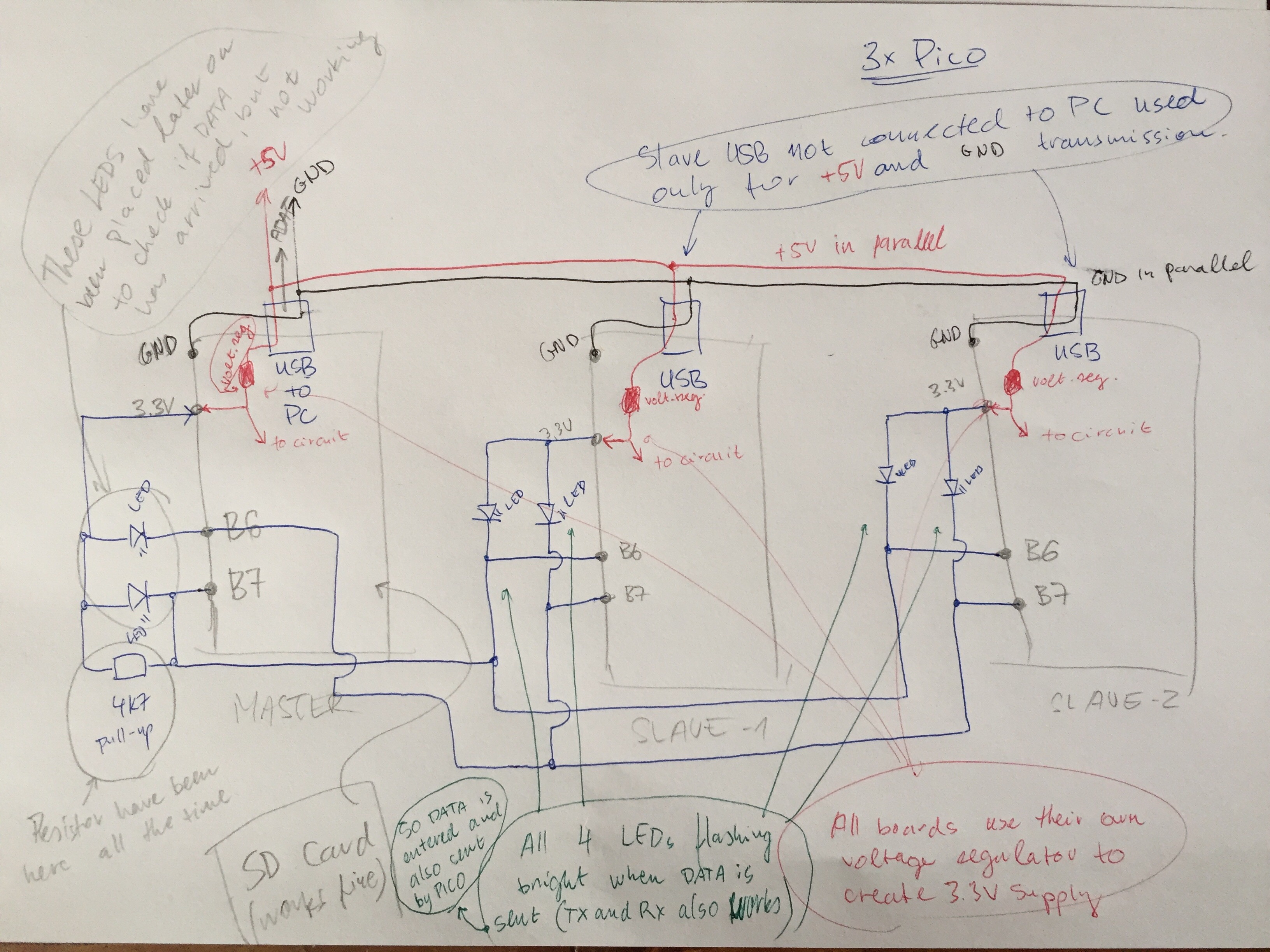
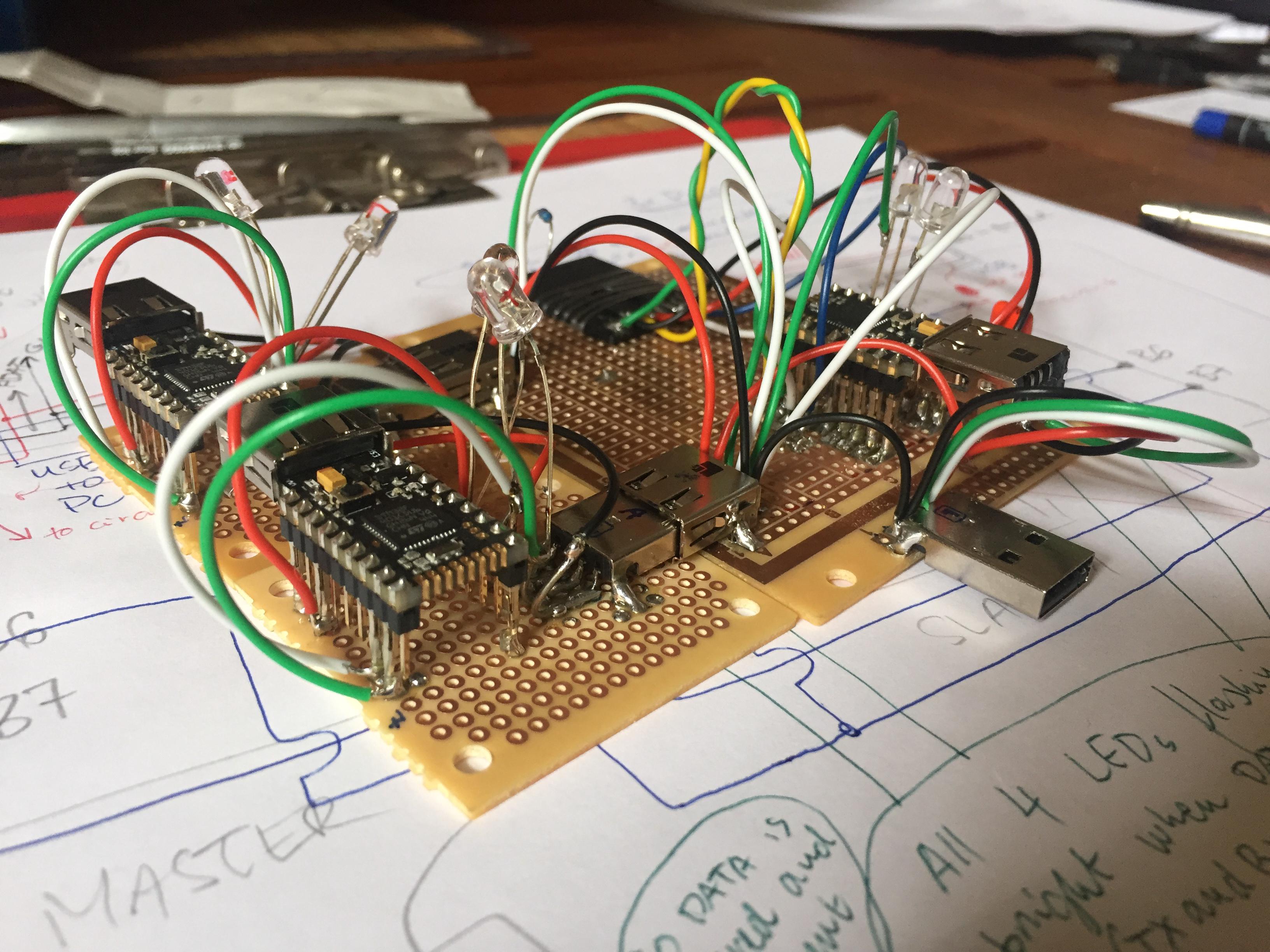
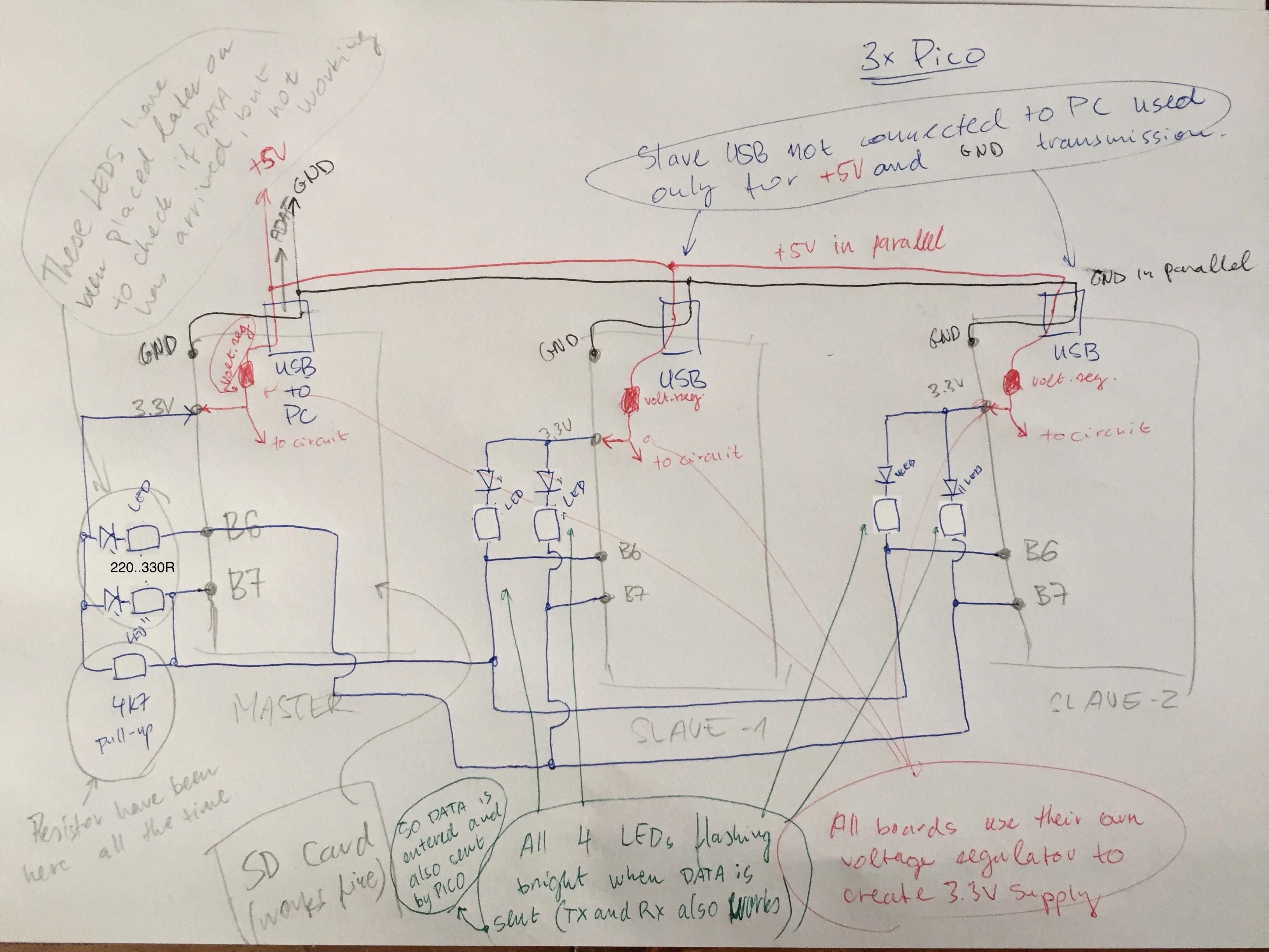
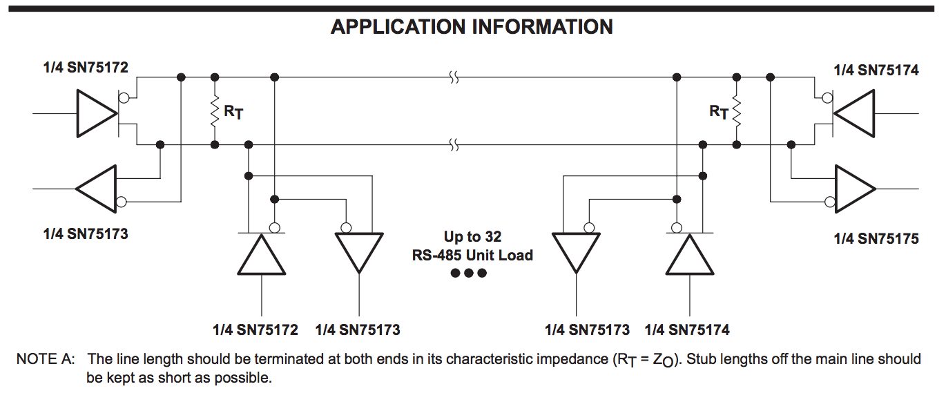
Posted at 2016-06-02 by Victor Thanks @gfwilliams this is really useful, I'll give it a go. Posted at 2016-07-28 by Picochu @gfwilliams, I have this set-up working as described by you, except getting responses from the Slave. What would the code be to send a response from Slave, and retrieve at Master? Posted at 2016-07-28 by @gfwilliams On the master, it's just: And on the slave, make sure Posted at 2016-07-28 by @gfwilliams So, Posted at 2016-07-29 by Picochu @gfwilliams, this works great when I have one slave... I can send data back and forth, thank you. When I have multiple slaves, I can still send data to all of them and run commands individually on each slave. However, for some reason, with multiple slaves, I cannot send data back to the master when the slave B6-s (with 4.7K resistors going to 3.3v) are wired together and go to master B7. It still works if only one slave goes to master. Any thoughts on what I might be doing wrong? Also, I made sure that only one slave responds at a time... in other words when I send a command to a slave, only that slave responds. Posted at 2016-07-29 by @gfwilliams Have you got Posted at 2016-07-29 by Picochu Incredible, that was it... I moved pinMode(B6, 'af_opendrain') into onInit. I have encountered this before several times where initialization or configuration of things had to be moved into onInit for things to work properly. Thanks again @gfwilliams Posted at 2016-07-29 by @gfwilliams Ahh - looks like it's a bug ('af_opendrain' doesn't get remembered) I'll file a bug for that and will try to get it fixed for the next release Posted at 2016-07-29 by @allObjects @gfwilliams, I think it is convenient that Posted at 2016-10-11 by Victor We have been experimenting with multiple slaves using the information above but are unable to get the response working with more than one. (Same issue @user66543 was having) The strange thing is whenever uncomment the pinMode function communication does not work at all. Is this the correct way to use on init below? Posted at 2016-10-11 by @gfwilliams I'd actually remove You do need Posted at 2016-10-11 by Victor We are currently using the below code with no success. The slaves are connected through a USB connector so do we need a 4.7k pull-up resistor on each slave or just once? (Currently we have one) Posted at 2016-10-12 by @gfwilliams What do you mean by connected through a USB connector? Also, how are you powering the slaves? If you have them plugged into a PC via USB then the console will automatically move to USB, so they won't respond on serial. A single 4k7 pullup should be fine though. You need to be careful that all slaves are running that code - if just one isn't in Posted at 2016-10-12 by Victor We're using a M and F USB to connect the slave boards together. (I assume this shouldn't affect anything) We only have the master plugged into the PC. (Is this what the USB.setConsole is for?) Posted at 2016-10-12 by @gfwilliams But you're still just using GND, VCC, B6 and B7? And these are Pico boards? Posted at 2016-10-12 by Victor Yes, they all have common GND and VCC, we have 3 Picos connected and B6 and B7 are wired as your instructions. Posted at 2016-10-12 by @gfwilliams Ok - I'd just assumed you might be using the USB connector on the Pico :) Perhaps you could attach a LED beween 3.3v and B6 on the slaves to help debug? You could also add: to the slaves. If all is going well, the LED should be off normally (data line is high). When you press the button the slaves should transmit some data and the LED should flicker. Posted at 2016-10-12 by Victor Sorry to keep bothering you. We connected LEDs and they seem to be flashing correctly. (Apart from slaves send back to master in which case slave send flashes but master receive does not) I've attached a couple of pictures of our designs and I was just wondering if you could have a quick look. I believe it may be something with the electronics as our testing results seem quite inconsistent. Thanks! Attachments: Posted at 2016-10-12 by @gfwilliams The circuit itself looks fine... However, I'd try putting a 200 Ohm (roughly) resistor in series with each LED you intend to keep connected. While just putting an LED on is ok as a quick hack for indication, the LED itself will stop the signal completely going down to 0, which may stop the signal from being received. But if one LED attached to the slave TX (B6) is flashing, but the one attached to master RX (B7) isn't - that just sounds to me like a bad connection? Have you checked with a meter to see if they are physically connected? (Having said that, because the LEDs without resistsors can stop the voltage going to 0, if you have differen colour LEDs then it might be a red herring - one will light while the other stays off) Posted at 2016-10-12 by Victor So we've found a few things but I'm not sure if they are any help. Master receive LED is flashing but barely. (Slave is sending but master not receiving) Does it matter that three different voltage regulators are being used with the three picos. May we need to connect them up afterward the regular in parallel? May we need more pull up resistors if there are more slaves? Posted at 2016-10-13 by @gfwilliams It shouldn't matter that the voltage regulators are unconnected, as long as GND is connected together. Did you add series resistors to the LEDs? As in my post above, that might explain why the receive LED isn't lighting and why you're not actually receiving data with the LEDs attached. Have you used a meter with a continuity check between B6 on the master and B7 on the slaves? Right now it seems that pullup resistors are not the problem - if the LED isn't lighting at the master, it's to do with pulling down to 0 rather than pulling up. With a lot of slaves you might need a bigger pullup resistor, but at some point and with longer lengths of wire, you'll probably need to start using special line drivers like RS485 - over longer distances and with more nodes, you'll get more noise coming in, which won't be good to feed straight into the Picos. Posted at 2016-10-13 by @allObjects In your test setup as shown in the picture, I assume you can check with a multi meter the connectivity of all slave RX and master TX, and also the connectivity of all slave TX and master RX. If so, you need only one LED and 220..330 Ohm in series connected from 3.3 to each master RX and master TX to see when something goes on. Having no resistor what so ever in series with the LEDs and having 3 LEDs on each master RX and master TX lines, the active pin is overloaded and does not guarantee anymore a clear LOW - the LED may still light, though. That you see the LEDs unequally lit on either master RX and master TX lines indicates that they vary significantly in (forward) voltage drop... and the one with the lowest prevents the other ones not getting the voltage anymore to light 'equally'. Adding resistors already helps... The (forward) voltage drop of LED vary with the color. As @gfwilliams points out, for long lines you would need some drivers that can handle noise. You then can add LEDs in series with a resistors to each RX and TX of each Espruino. With suggested RS485 drivers you need then four wires - two twisted pairs - to get the optimal communication. Attachments: |
Beta Was this translation helpful? Give feedback.
Uh oh!
There was an error while loading. Please reload this page.
-
Posted at 2016-06-02 by Victor
Hi,
I'm just wondering if anyone has any insight on one master Espruino pico communicating with four slave Espruino pico devices.
I'm currently looking at I2C though the documentation says "master only".
Or would I be able to use serial communication with multiple devices? (I assume I would need to implement an addressing system in the program myself)
Thanks,
Victor
Beta Was this translation helpful? Give feedback.
All reactions