[SOLVED]L293D Control Two Micro Metal Gearmotor HP #5927
Replies: 1 comment
-
|
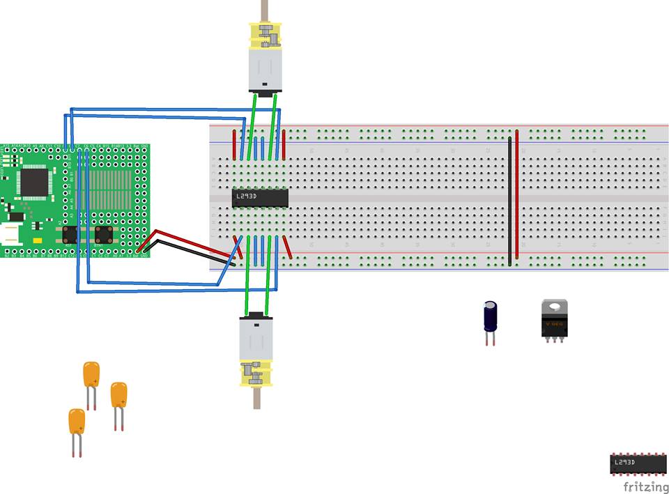
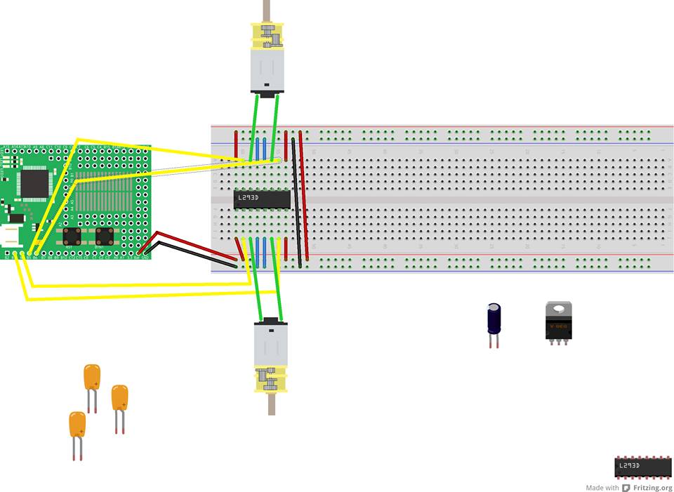
Posted at 2014-04-27 by jacklee I have capture a images for detail Attachments: Posted at 2014-04-27 by MrTimcakes Forgive me if i am wrong, but it looks like you don't have your motors connected to a ground. You have them hooked up to an output that is powered. Posted at 2014-04-27 by jacklee Hi, Ducky thank for reply. Posted at 2014-04-27 by jacklee I have Change my Circuit to the Following. But the Gearmotor is still not working Attachments: Posted at 2014-04-27 by MrTimcakes Oh, i dind't spot that you hadn't connected the power to the espruino. What happens if you attach one of the motor terminals to GND? Posted at 2014-04-27 by MrTimcakes i found this, http://fritzing.org/projects/arduino-l293d its for arduino but it might help you. Posted at 2014-04-28 by @gfwilliams @ducky The idea of the L293D is that the motor can have both sides connected to the controller - so you can run the motor in reverse. @jacklee that circuit and code looks absolutely fine to me. Is the motor rated for 5v, or some higher voltage? Perhaps you could check with a meter and see if one side of the motor really is at 5v, and the other is at gnd? Posted at 2014-04-28 by jacklee @ducky Thank You for you information and reply. First: in bread board, power circuit(+,-)is separated at half point so i need to make the far right two wire near. The unsolved issue is i can't solve when i using [C6,C7,C8,C9] or [C6,C7,C4,C5] I need to code like below to stop both of the motor I have testing few hours in [C6,C7,C8,C9] and [C6,C7,C4,C5] this two group. After few hours I change my Circuit PIN to B3,B4,B5,B6 and code like below is work properly for me Both motor is Run Both motor is Stop I have No Idea why the PIN in the "C" is not working properly but the PIN in "B" is working Good? Attachments: Posted at 2014-04-28 by @gfwilliams I'm afraid I have no idea! I just tested here and C4/5/6/7 outputs output the correct values with digitalWrite. Maybe there is some kind of short on your board, but we test for that in manufacturing. Can you check the outputs with an LED (L293D doesn't have to be connected) and see if they output the correct values? Posted at 2014-05-01 by jacklee @gfwilliams Hi, I Found what is the issue . is my fault when i solder the pin header to Espruino not correct. their still have some gap. I have use a LED test by All PIN is working Fine Now Posted at 2014-05-01 by @gfwilliams Great, thanks for letting me know! Posted at 2014-06-18 by gnz Thanks @jacklee for this thread and for your diagrams! It helped me get the L293D working! You should consider turning it into a tutorial on the espruino page, because there is no other explanation about using the L293D on a breadboard (instead of soldering it to the espruino). Posted at 2014-06-19 by Pumych Hi @jacklee, can I ask what is this software that you using to draw the circuits? Posted at 2014-06-19 by @gfwilliams @Pumych it's probably Fritzing Posted at 2014-06-19 by Pumych I must to say that I inspired by Espruino (because of JavaScript) to learn new interesting things. Thank you. Posted at 2014-06-19 by jacklee @GNZ I happy my Post is helping you, Good Idea Yes i should turning it into a tutorial. @Pumych Yes, i using Fritzing and Illustrator for the circuits. Posted at 2018-05-21 by user90026 :/ Sorry to be posting this out of nowhere, but could you please share the fritzing part for the micrometal motors? I can't seem to find them anywhere. TIA |
Beta Was this translation helpful? Give feedback.
Uh oh!
There was an error while loading. Please reload this page.
-
Posted at 2014-04-27 by jacklee
Hello,
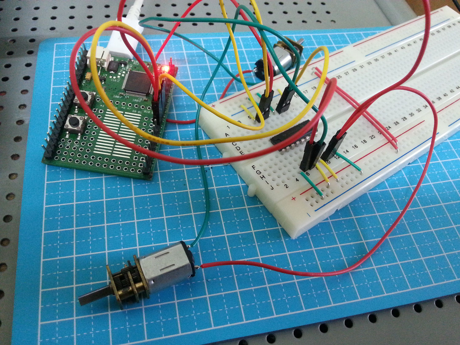
I using a L293D chip(16 pin) to control two 298:1 Micro Metal Gearmotor.
the following attach files is my Circuit.
Any i refer the http://www.espruino.com/L293D and write my code like below
but when send to Espruino to LED is LightUp but the GearMotor still not work is it any step i missing?
Attachments:
Beta Was this translation helpful? Give feedback.
All reactions