Pre Charge (Resistor) required when Inverter is getting switched on? #145
Replies: 14 comments 56 replies
-
Good question, in the Forum of akkudoktor you can also find some discussions regarding this: https://www.akkudoktor.net/forum/neue-ideen/micro-inverter-an-batteriespeicher-betreiben/ I don't think that you can destroy the battery, because the time until the resistors are loaded is probably just too short to damage the battery. But it could be a problem for the capacitors, because batteries are not officially supported on the Hoymiles micro inverters and the manafacturer probably didn't implement a current limiting for the capacitors. You can only use Hoymiles with a battery at your own risk. For this reason I would not use any relais in my circuit or let the voltage guard for daily cutoff. I was looking for an automatic precharge circuit for some time, but didn't find anything working out of the box or maybe just one thing that was quite expensive, don't remember anymore. My personal recommendation (how I do it):
I personally use a Pylontech battery. I bought it because it was advertised with current limiting and a soft-start feature. |
Beta Was this translation helpful? Give feedback.
-
|
I use a HM-300 and maybe you could use a HM-600 without pre-charge. But I doubt, that you should try it with big kw inverters. Everything is on your own risk, because we are outside of the intended use case scenarios of the manufactures. But I think @berni2288 recommendations are good. |
Beta Was this translation helpful? Give feedback.
-
|
Thanks much both! I'll get back with more thoughts. At the moment I am using a HM1500 and 4x 385Wp Panels and a combination of Ahoy, Shelly 3em and Plus to monitor. However, I am wasting 60-75% of the produced energy so was also considering a Pylontech. |
Beta Was this translation helpful? Give feedback.
-
|
@berni2288 How does the setup handle situations like this:
At the same time, panels produce: A.) 600W - Will these 600W go straight into the battery or will 500W from the MPPT go straight into the inverter and the remaining 100W will go into the battery? I am trying to grasp the flow of energy in the system and how it handles situations where the panels produce enough or more energy that needed in the household. I am thinking that this need should go straight into the inverter, without going into the battery first. Is this possible or is all energy going into the battery first? And when the battery is full all additionally produced energy is absorbed (wasted)? B.) 300W - Will the 300W go into the battery first and then the battery is feeding 500W into the inverter? Or will the 300W go straight into the inverter and the inverter pulls the gap of 200W from the battery? I hope I could address my points or level of unclarity in an understandable fashion. |
Beta Was this translation helpful? Give feedback.
-
|
It's quite easy. Electrons always seek the path with the lowest resistance and lower voltage. The inverter has a lower resistance (as long as it's pulling power) and will always be fed first and the remaining power goes into the battery. That's true at least when the inverter, battery and charger are in the same curcuit without any components inbetween. The energy from the charger always takes priority because it has a higher voltage than the battery. So this energy flows either into the inverter or into the battery. I think the efficiency is 95% most of the time. It's true that the ougoing and ingoing inverter powers are not the same and this is not considered at the moment. A) Only the remaining power will go into the battery. When the battery is full and the inverter limit is too low, the energy from the Solar panel will be blocked by the charger & lost. We don't have a logic implemented yet in such a case, that would set the inverter limit higher to let the excess energy flow into the public grid. B) The inverter would take only 200W from the battery. |
Beta Was this translation helpful? Give feedback.
-
|
Regarding your answer re: B) "The inverter would take only 200W from the battery" - And the 300W from the panels would still flow to the inverter like you described above? So the Inverter would feed 500W into the household. |
Beta Was this translation helpful? Give feedback.
-
|
A) I understand, that is not easy to do It because we don't realy have information how much energy we wasting in the moment. |
Beta Was this translation helpful? Give feedback.
-
|
Some time ago I found a power limiter board on this discord channel: https://discord.com/channels/984173303147155506/1060347063281401876/1080114933473222779 IMHO this is exactly what's necessary when your battery has no soft-start function. |
Beta Was this translation helpful? Give feedback.
-
|
Send me a PM (martin.dummer at gmx.net) and I send you the .zip with the gerber files. |
Beta Was this translation helpful? Give feedback.
-
|
Hi, IRFZ34 can only 55V and 26A... |
Beta Was this translation helpful? Give feedback.
-
|
For a night feeding setup with 100-150W this should be fine though? I came across this one today: https://www.bicker.de/en/be-dceb10a_dc_inrush_current_limiter_10-30vdc_10a_open_frame?nbnet=0# Good for 12/24V setups I think. |
Beta Was this translation helpful? Give feedback.
-
|
That BE-DCEB10A looks good to me if the power is enough for you and you use 24V. 14V won't work with Hoymiles tho. |
Beta Was this translation helpful? Give feedback.
-
|
Right. That was my thinking too, 20% discharge limit at 25,6V x 5,8A should get me close to 150W, leaving enough room to not stress the hardware to much. I think I would still add a battery protect and a 16A inline fuse (Schmelzsicherung) after the limiter. |
Beta Was this translation helpful? Give feedback.
-
|
What if the battery would be always connected? I would only switch the inverter on the AC side if the SOC (or battery voltage) would drop below limits. Then charge the battery and only switch the inverter AC on when the battery is charged. |
Beta Was this translation helpful? Give feedback.
-
|
Then you only have the high current problem at the first time :) I'm not an expert on this tho... I don't know how much the inverter capacitors can handle... and if the problem actually exists. Better read some other forums. I've decided for myself to not take any risk because I don't want a broken Hoymiles inverter after 3 years of usage already. |
Beta Was this translation helpful? Give feedback.
-
|
@swingstate when you connect your "any battery" directly to the inverter (with a fuse in between!!!) then you have the problem that a malfunction may drain your battery to 0 volt - and then the battery will be damaged. |
Beta Was this translation helpful? Give feedback.
-
|
well yes, but that proves this is good solution. :) |
Beta Was this translation helpful? Give feedback.
-
|
most BMS can switch off at under voltage, but only few BMS can "soft start"...if any... |
Beta Was this translation helpful? Give feedback.
-
|
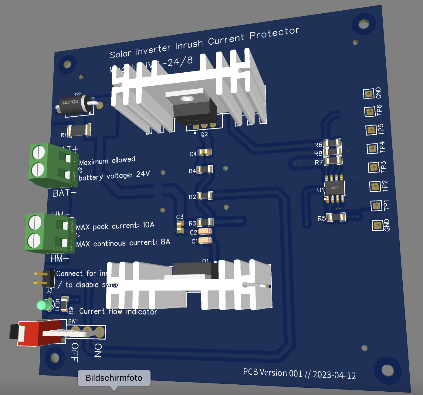
Prototyped a PCB based on the discussion and files shared above. Lets see how this plays out.
|
Beta Was this translation helpful? Give feedback.
-
|
the akkudoktor forum is full of complains, that Hoymiles consumes around 13A at 24V if connected to battery. |
Beta Was this translation helpful? Give feedback.
-
|
yes next revision should support both 24/48V |
Beta Was this translation helpful? Give feedback.
-
Yes you are missing the fact that the 11.5 A are per input connector, and the HM-1500 has four inputs..... |
Beta Was this translation helpful? Give feedback.
-
|
yes, I am aware and was referring to 1 connector. |
Beta Was this translation helpful? Give feedback.
-
|
I am testing with a HM-300 first, which has only 1 connector. Also to keep costs for the pcb limited for the POC. |
Beta Was this translation helpful? Give feedback.
-
|
Why not use an relay with 30A (they are relative cheap vor 24V) where the NO is connected to the inverter and the NC is connected via an an pre charge resistor to the inverter. Lest say the battery connects than the pre charge resistor would limit the current in to the inverter. If the input voltage is above lets say Vbat -20 % turn on the relay? After the Relais is turned on we are ready to set the power limit. I think therefore its the best to make sure that the inverter has 0W output at the restart configured. This would only need 1 pin and 1 relay more plus an InverterInrushCurrentLimitter or SoftStart-Function (you name it^^) in the program? All required data is coming from the Inverter already so we can use it. Maybe the time it takes to start up the inverter and talk for the first time to the system would be enough, so that there is no need to use the Vbat -20% trigger? Can any one tell who long it takes for an 48V system? |
Beta Was this translation helpful? Give feedback.
-
|
If I get your thought right - You are relying on the inverter and software + Relay & Resistor to manage the switching moment properly? My approach is probably more general - I don't want to allow more than 10A (peak) to reach the inverter. No matter what kind of inverter it is. Hence the pcb. |
Beta Was this translation helpful? Give feedback.
-
|
the problem with relay is: the coil need power, 1-2W on small relais (24V) and up to 15W on big contactors that can handle up to 60V... |
Beta Was this translation helpful? Give feedback.
-
|
And relay contacts have a significant resistance, so the they cause another loss of power. Thats the main reason why a solution with MOSFETS is much more desirable. |
Beta Was this translation helpful? Give feedback.
-
|
Initially i wanted to use an JD2912-48V-1Z for an 48V system which will switch at min (60%) 28.8V and can handle 7A switching current at this voltage. In any case i would use an 68 Ohm 100W resistor to precharge. With this i will only have max 0.86A. So no Problem on the switching power side. |
Beta Was this translation helpful? Give feedback.
-
|
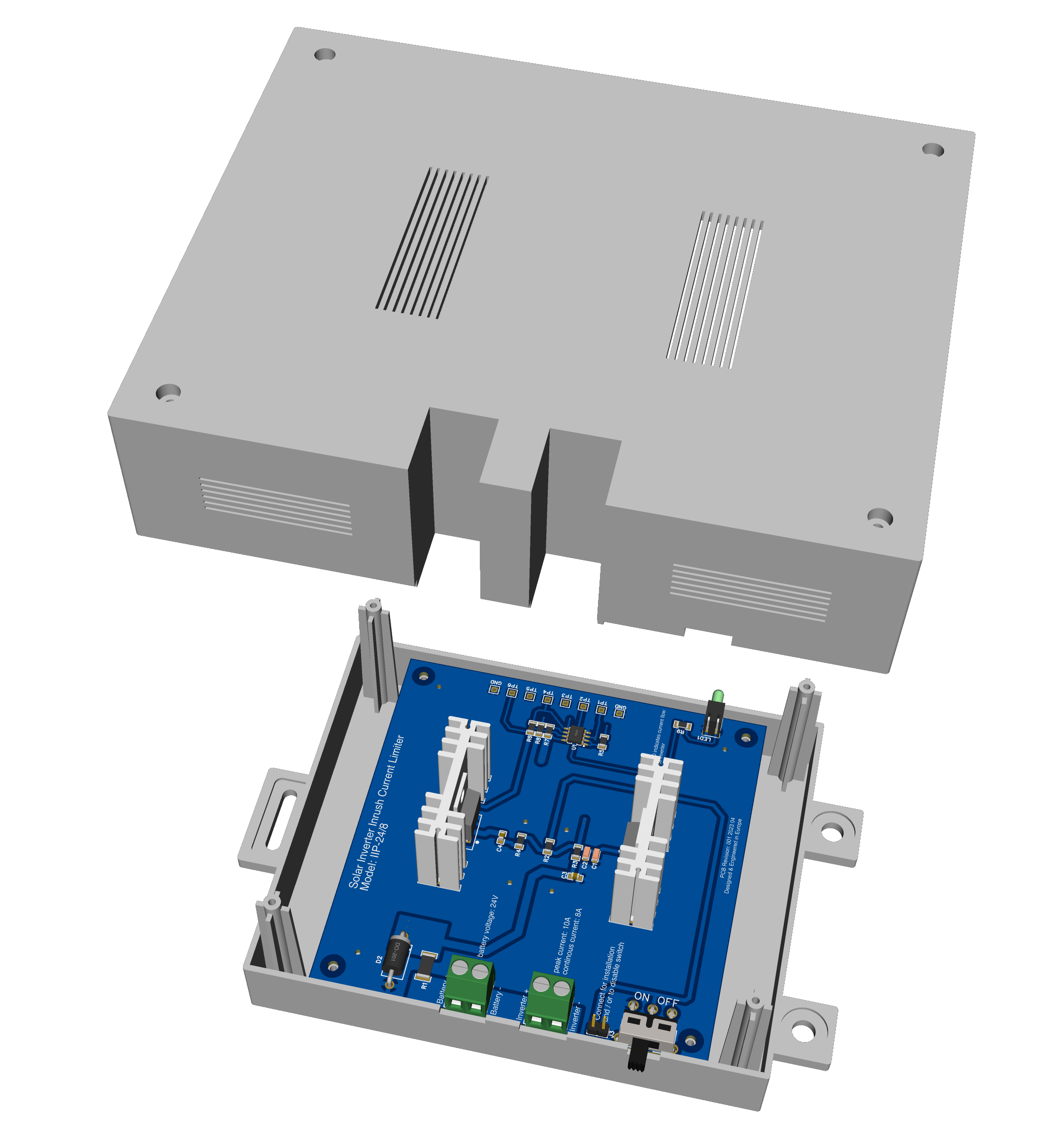
Final version of the single channel version which I ordered. Still need to find a reasonable shop to print a case.
|
Beta Was this translation helpful? Give feedback.
-
|
Which Transistor you want to use? An TIP35?. Than there should be 11,5A continous current no Problem. |
Beta Was this translation helpful? Give feedback.
-
|
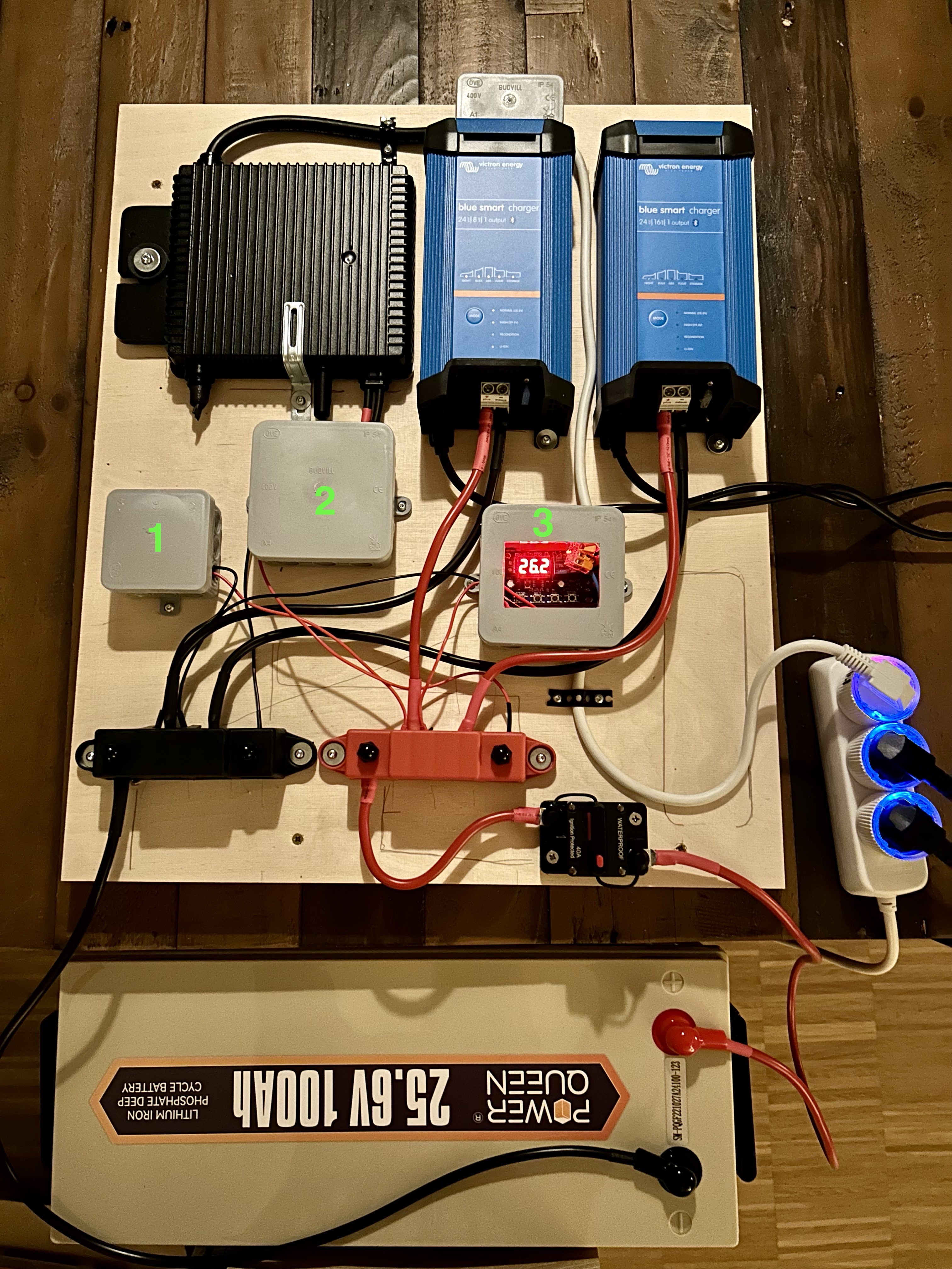
IRFZ34PBF Current status of 24V Setup with HM-300, 16A & 8A AC chargers: 1 - Shelly UNI to monitor Battery SOC in Homeassistant
|
Beta Was this translation helpful? Give feedback.
-
|
Im Akkudoktor Forum wurde gerade interessante und dabei sehr einfache Lösung vorgeschlagen (wobei die Schaltung aus einem anderem Forum stand) Es sind nur wenige Bauteile nötig, und die Verlustleistung hält sich in Grenzen |
Beta Was this translation helpful? Give feedback.
-
|
Wenn man die Gate Kapazitäten berücksichtigt und die Widerstände entsprechend dimensioniert kann man sogar den Kondensator weg lassen^^ |
Beta Was this translation helpful? Give feedback.
-
|
ich weiss nicht, ob ich es hier schon gefragt habe? Das Ladegerät liefert maximal etwas mehr als die Leckströme und Selbstentladung + hält die Batterie auch im Winter auf ca. 18V. Die Längsdiode verhindert, dass die Solarpanels oder eine über 18V geladene Batterie das Ladegerät grillen. Mein Problem dabei: Seit 1993 habe ich keine Induktivitäten und keine Kondensator-Ladekurven mehr berechnet. Habe echt kaum noch einen Plan, wie das ging. Die Elkos im HM-300 dürften inzwischen bekannt sein, irgendwer hatte mal einen aufgeschraubt. 2x 20.000µF meine ich, gelesen zu haben, kann das hinkommen? Die zweite, noch beklopptere Idee wäre, ein zweites 12..18V Netzteil (ich sage hier absichtlich nicht "Ladegerät", ob wohl das auch ginge) an den HM-Eingang zu hängen, um die Elkos bei Laune zu halten. Wenn man mit Dioden arbeitet, kann man das sogar aus dem selben LG holen, das die Batterie über den Winter rettet. Je nach Diode gehen da auch paar mW in Abwärme, aber das ist einfacher und weniger Fehleranfällig, als die MOSFET-Lösung, nicht wahr? Diskussion willkommen! |
Beta Was this translation helpful? Give feedback.
-
|
Ich habe mal was in einer Simulation bei falstad zusammengeklickt.
Die Werte sind alle total aus der Luft gegriffen, der 10R müßte z.B. 4..5 R sein. Aber wir kennen den Alko ja auch nicht. Ich wollte nur sehen, wann das System prinzipiell funktioniert oder ob es schwingt. Z.B. ohne Freilaufdiode zerballert es den Elko in bestimmten Situationen. Die Schaltung, um die es geht, besteht in Echt also nur aus dem 18V Netzteil, 2 normalen kleinen Schottky-Dioden (dimensioniert am Kurzschlustrom des Netzteils), der Spule und deren Freilaufdiode. Zur Dimensionierung der beiden Schottkys könnte man noch einen Längswiderstand ins 18V Netzteil einhängen, das soll ja nur Spannungen aufrecht erhalten und nix Großes leisten. Dito bei der Freilaufdiode. Ich weiss nicht, was man bei einer 1mH Spule für Abschaltströme erwarten muss - in der Simulation baute sich ohne Freilauf eine Spannung bis 10-fach der Ladespannung auf. |


Beta Was this translation helpful? Give feedback.
-
|
soll ich meinen HM300 mal aufschrauben und ablichten? |
Beta Was this translation helpful? Give feedback.
-
|
Hmmmm ... das wäre hilfreich und äußerst interessant, aber ehrlich gesagt möchte ich Dich nicht dazu verleiten, an 230V Technik zu schrauben! Vielleicht sollten wir die Diskussion nach Discord in den BMS-Channel zu Ahoy/OpenDTU verlegen? |
Beta Was this translation helpful? Give feedback.
-
bringt nichts, der ist voll mit Gummiartigem Zeug vergossen, das du ohne Zerstörung nicht wegbekommst. |
Beta Was this translation helpful? Give feedback.
-
guter Tipp, danke! Die Hoymiles-Schaltung leuchtet mir auch etwas mehr ein: während ein Paar mit seinen in Summe 5400µF gerade entlädt, ist das andere Paar "ausgangsseitig" hochohmig belastet und kann sich am Solar-Panel aufladen. Dann wird getauscht. |
Beta Was this translation helpful? Give feedback.
-
|
und was ist mit NTCs? Es gäbe übrigens auch schon fertige Limiter, als fertige Bauteile von VPT oder Loreme ... nur schwer, an einen Distri zu kommen. |
Beta Was this translation helpful? Give feedback.
-
|
Die NTCs scheinen doch schon ein bisschen Wärme zu erzeugen. Nichts für 10A (obwohl es auch dafür welche gibt) |
Beta Was this translation helpful? Give feedback.
-
|
Hallo, Der MPPT 75/15 hat eine "Sanft-Einschaltung". Theoretisch kann er eine elektrische Ladung von ca. 0,1As liefern. HM-300 direkt an MPPT75/15 geht also nicht. Aber... die Nennleistung von 300W sind auch noch ein Problem Vermutlich muss ich doch den HM-300 direkt an den LiFePo4 anschließen. @modem-man-gmx Im NTC Datenblatt findet man normalerweise eine Kennlinie, die den Widerstand bei einem |
Beta Was this translation helpful? Give feedback.
-
|
Das kann ich nicht pauschal beantworten. Es kommt auf den Typen an. Über den Daumen würde ich mit einer Halbierung des Widerstandswertes zwischen 30-60°C rechnen. Auch im Winter sehe ich kein Problem. Im Anhang findest du ein Datenblatt. |
Beta Was this translation helpful? Give feedback.
-
|
Der B57364S0109M000 sieht ja schon Lecker aus! Man könnte auch 2 oder 4 parallel schalten, wenn man die Schaltung unklimatisiert aufstellt (Stall statt Keller). |
Beta Was this translation helpful? Give feedback.
-
|
Hilf mir mal, da war doch noch so eine Wurzel-2-Sache zwischen V_peak und V_effective ...? |
Beta Was this translation helpful? Give feedback.
-
|
Beta Was this translation helpful? Give feedback.
-
|
Stimmt, NTCs pegeln sich parallel nicht ein sondern laufen auseinander. Oh Mann, das wußte ich vor 30 Jahren noch aus dem FF. Ich werde alt. :-( |
Beta Was this translation helpful? Give feedback.
-
|
So ganz verstanden habe ich noch nicht warum der HM-300 15.5A zieht. Laut Datenblatt sind es 11.5 A. Das entspricht auch ziemlich gut der Leistung, die ich aus dem Inverter mit meiner 24V Batterie bekomme, wenn ich noch ca. 5% Verlust (DC->AC) mit einberechne: 24V * 11.5 A * 0.95 = 262 W AC |
Beta Was this translation helpful? Give feedback.
-
|
Ja, ich habe auch noch Zweifel ob das so stimmt was ich messe. Das würde bedeuten das die Ausgangsstromabschaltung des MPPT 75/15 eingreift. Kommende Woche probier ich das aus. |
Beta Was this translation helpful? Give feedback.
-
|
hier sollte die wURZEL-"-fRAGE LANDEN |
Beta Was this translation helpful? Give feedback.
-
|
Wie würde sich der Victron 75/10 in der selben Situation schlagen? Der wird mit 10A maximal-Ladestrom angegeben, aber in vielen Tabellen auf der Webseite wird er - aus welchen Gründen auch immer - identisch zum /15 gelistet. Beim Victron ist mir auch nicht klar, ob die Stromstärke lediglich den Ladestrom in den Akku hinein bezeichnet und der Ausgang nur durch die Bauteilfestigkeit begrenzt wird. Weiss Du da etwas? |
Beta Was this translation helpful? Give feedback.
-
|
Das kann ich dir nicht sagen. Aber meine Messungen zeigen das der MPPT 75/15 mit dem HM-300 kein Problem hat und mit den Stromspitzen von ca 28A zurechtkommt. Genaueres kannst du im Kapitel "MPPT 75/15: Maximaler Dauerausgangsstrom" nachlesen. @helgeerbe : Die 11,5A die der HM-300 anzeigt stimmen nicht. Es sind über 14A / 320W. |
Beta Was this translation helpful? Give feedback.
-
|
Jetzt habe ich gerade gesehen das |
Beta Was this translation helpful? Give feedback.
Uh oh!
There was an error while loading. Please reload this page.
-
I am trying to grasp how onBattery works and whether there are still any risks to damage the inverter and/or battery when the system is switched on again, after it has been off due to a empty battery.
For example the battery has been drained over night and needs to be charged on the next day. How is this handled when the battery is full again? Will there/Can there be situations where high switch on currents can occur?
I came across this topic due to this post Here and comments on YT and other forums.
I don’t want to destroy the battery (or inverter) and wonder if additional hardware is required to enforce a soft start of the inverter.
I understand a battery protect is not intended to switch a inverter on the DC side.
What are your thoughts?
Beta Was this translation helpful? Give feedback.
All reactions