CAD and CAM workflow notes
Quick links
DISCLAIMER! This section is not intended to be complete guide to 2D/3D design or CAM, but rather a compilation of quality resources and knowledge specific to the CNC machine itself. The world of CAD/CAM can be a nightmarish rabbit-hole, but if you stay focused on your project(s) and buddy up with an experienced, friendly TC Maker member you can get stuff done easier than you'd think!
 Computer-aided design (CAD) is a piece of software that allows you to create 2D designs or 3D models that accurately represent the thing you want to create. Different programs are appropriate for different types of objects, though there are some general classifications of modelling that
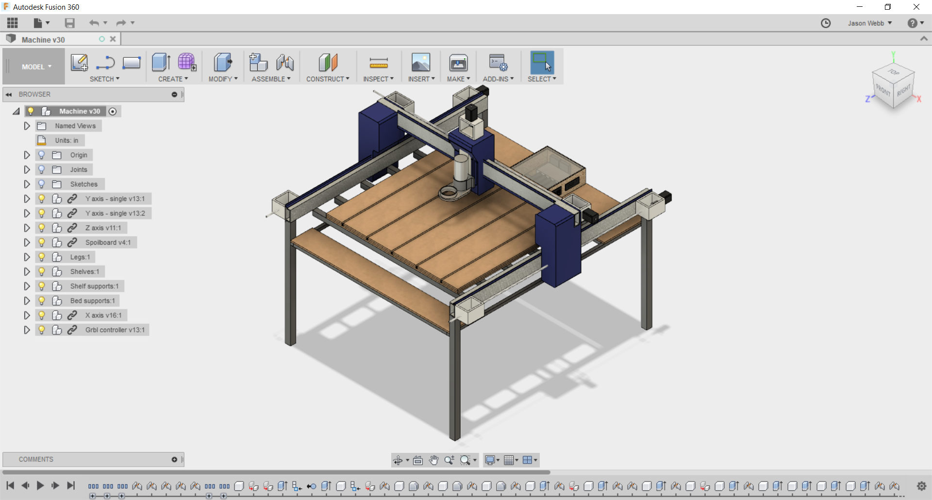
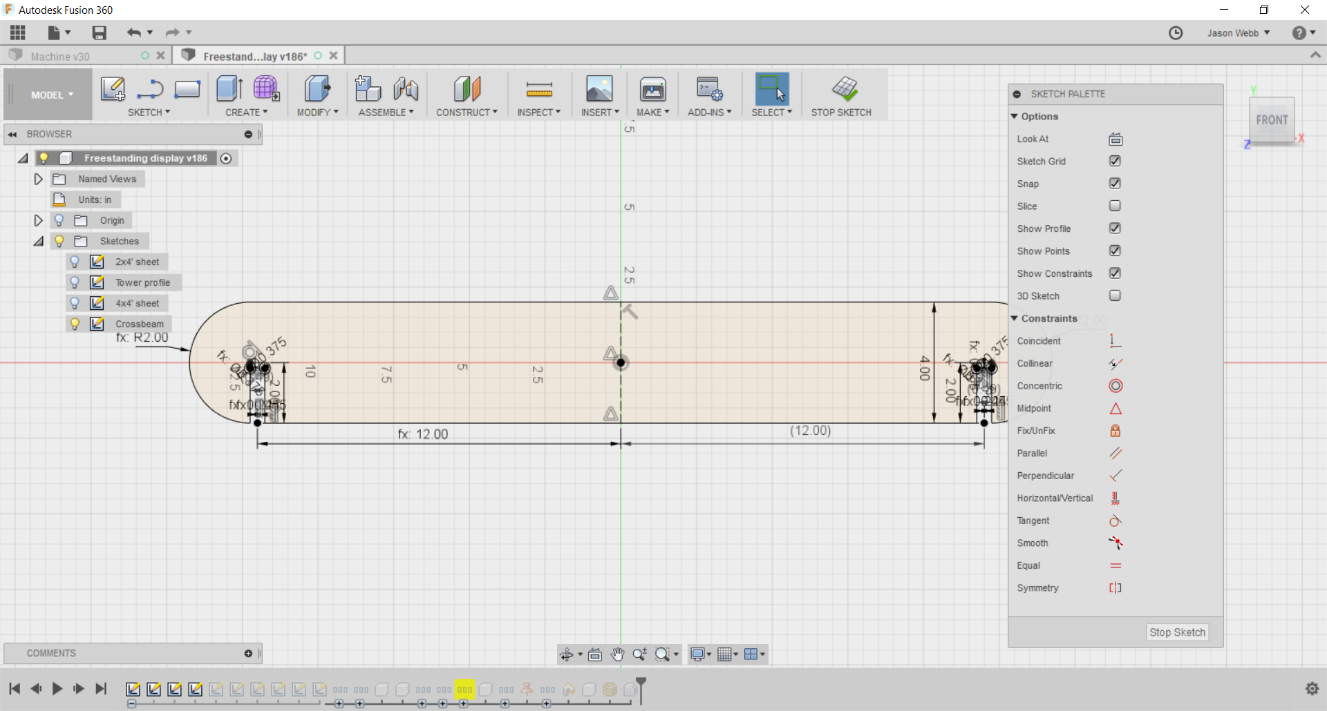
- Parametric modelling involves explicitly defining dimensions and relationships for geometry, allowing you to affect design features just by changing variables. The full history of the creation process is recorded and available at any time, allowing you to make important changes at any time. Tools like Fusion 360, Autocad are parametric modelers.
- Direct modelling involves creating models by building directly upon previous steps. Each change you make is directly integrated into whatever you were building on top of, effectively making these changes more or less permanent. Tools like Sketchup and Tinkercad are direct modelers.
- Organic or freeform modelling involves using more life-like processes to create highly expressive models in similar to how we would work with physical media like clay or wet sand. Dimensional accuracy and manufacturability are less emphasized than aesthetics. Tools like ZBrush and Meshmixer are organic modelers, though more traditional CAD packages (like Fusion 360, Solidworks, and Blender) are incorporating some freeform modelling techniques.
- Make sure your design is no larger than the X/Y/Z size of the machine. Give yourself a bit of extra space on all sides so you have time to hit the E-stop if things go bad.
- Think ahead to how you plan to secure your workpiece to the spoilboard, and make sure you have enough extra room in your design for clamps, plastic nails, or other fixturing tools.
- If you want to use a piece of CAD software that you haven't seen many people use for CNC work, test it out with your CAM program before you invest too much effort in it.
- Always consider the size of the end mill(s) / router bit(s) you plan to use to fabricate your part while you are designing. Is there enough space for it to get in there and move around?
 Just about any vector art program that can output in the vanilla SVG or DXF format can work for CNC. However, some low-end design software (like Inkscape) can sometimes do a bad job of exporting with the right version or flavor of SVG/DXF that is expected by your CAM software.
- Fusion 360
- Illustrator ($$$)
- Vectric Cut2D or VCarve ($$$)
- Inkscape
- Easel (web-based)
- MakerCAM (web-based)
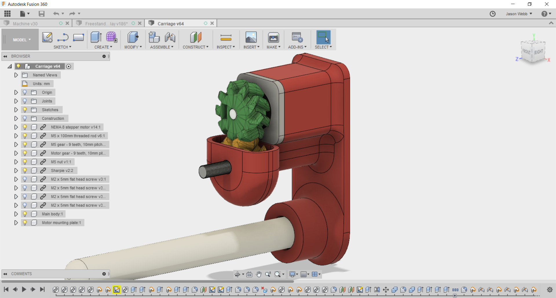 Whichever program you choose to use for 3D modeling should be capable outputting manifold (watertight), well-formed STL or OBJ models.
- Fusion 360 (recommended)
- Tinkercad (web-based)
- Onshape (web-based)
- OpenSCAD
- Blender - tricky to get units and file format correct, but very powerful for organic modelling!
- Rhinoceros ($$$) - add Grasshopper for extra awesomeness!
- Meshmixer
- Sketchup is NOT recommended, as it does not do a good job of exporting 3D models for use elsewhere.
Industry-level 3D modeling and animation packages like Maya, 3DSMax, and Cinema4D might also be used, but tend to do a bad job of exporting well-formed manifold meshes necessary for fabrication.
| Program | Tutorial |
|---|---|
| Fusion 360 | Learn Fusion 360 in 60 Minutes |
 Computer-aided manufacturing (CAM) is a piece of software that takes as input either a 2D or 3D design file (made in a CAD program) and generates toolpaths (G-code) for the machine to follow in order to carve that design into or out of a piece of material (called "stock").
In production environments CAM is taken extremely seriously and can cost many thousands of dollars and take a very long time to learn how to do well. The more efficient the toolpaths, the more parts you can produce per hour, which means more profit.
However TC Maker is not a production environment, so we don't need to as obsessed with efficiency. This means that we have a lot more (and cheaper) software options available. Though this is a bit of a double-edged sword - for every free, easy-to-use CAM package there are likely dozens that are pretty unpleasant to use and require a huge amount of overly-specific knowledge.
- Tabs are your friend! Use them whenever you can to prevent loose parts from flying across the room or worse, damaging the machine.
- Don't get too ambitious with speeds, feeds and cut depths. This is not a production-quality machine, so don't push it like one.
[TODO: what kinds of generalized tips can we give newbies about how fast the machine can cut common materials? Any ballpark figures for speeds and feeds?]
| Category | Parameters | Notes | ||||||||||||
|---|---|---|---|---|---|---|---|---|---|---|---|---|---|---|
| Wood |
|
Too slow and the wood will get burned. Too hot and the bit can heat up and weaken, even break, over time. |
||||||||||||
| Plastic |
|
|||||||||||||
| Foams |
|
- gcodetools for Inkscape
- Easel (web-based)
- MakerCAM (web-based)
- Fusion 360 (recommended)
- MeshCAM ($$$)
- Vectric Cut2D or VCarve ($$$)
- CamBam ($$$)
A post processor is a piece of software that alters the initial raw G-code created by the CAM software by adding any proprietary codes or formatting that your particular CNC machine expects. Most of the time this functionality is built into whatever CAM program you are using, but its good to be aware of this step.
Regardless of the CAM package you choose, try to make sure that the G-code you end up with is in the LinuxCNC or EMC2 format. If you don't know, that's OK - you can simulate the G-code on the CNC machine's computer before trying to run it!
| Program | Tutorial |
|---|---|
| Fusion 360 | - Overview of Fusion 360 for CNC Routers (Chair Design) - CNC Router with Fusion 360, Bookshelf Tutorial |