Network socket #10986
Replies: 2 comments 1 reply
-
|
I would represent these wall sockets as separate Devices, each with one Front Port and one Rear Port. Then the far-end room has another such device, and the Rear Ports are connected together with a cable. Alternatively, you could represent all the wall sockets in a room as a single 'Device', and just create multiple front ports and rear ports on this device.
What's at the other end of this port? If this is a "Circuit" from a telco provider, then you'd represent it as a "Circuit Termination" linked to a "Circuit". You can then create a cable from this Circuit Termination to the core switch. However, this is one area where Netbox's data model falls down though, in my opinion. A "Circuit Termination" is a logical entity, not a physical port (e.g. it doesn't have a port type). And yet to connect it, you create a Cable to it. This means that one end of the cable is connected to a logical entity with an unspecified type of port, while the other end is connected to a 1000baseT Interface or whatever. Furthermore, in reality, multiple provider "circuits" can be presented on a single physical port and cable. |
Beta Was this translation helpful? Give feedback.
-
|
My problem is, if I integrate the network socket, that I see then in the traceroute with the cables always only the next Job.
|
Beta Was this translation helpful? Give feedback.
-
|
Sorry, I don't understand what you mean. When you create the socket, first you create a Rear Port, then you create a Front Port which is linked to that Rear Port. This tells Netbox it is a pass-through connection. This gives you cable tracing through the socket. Therefore, if you connect the following three cables:
then a cable trace from switch A interface will show you three segments, ending up at the switch B interface. Try it! Also, in the switch A Interfaces table, there are two columns you can enable:
These columns are enabled with the "Configure Table" button. If you want other graphical options, there is also Netbox Topology Views plugin. Right now this only shows the cables+patch panels, but there is work underway to be able to show end-to-end connections too. |
Beta Was this translation helpful? Give feedback.
Uh oh!
There was an error while loading. Please reload this page.
-
Good morning,
I am just starting to use Netbox and I love it.
But now I come to a difficulty with a customer where I do not know exactly how to display it.
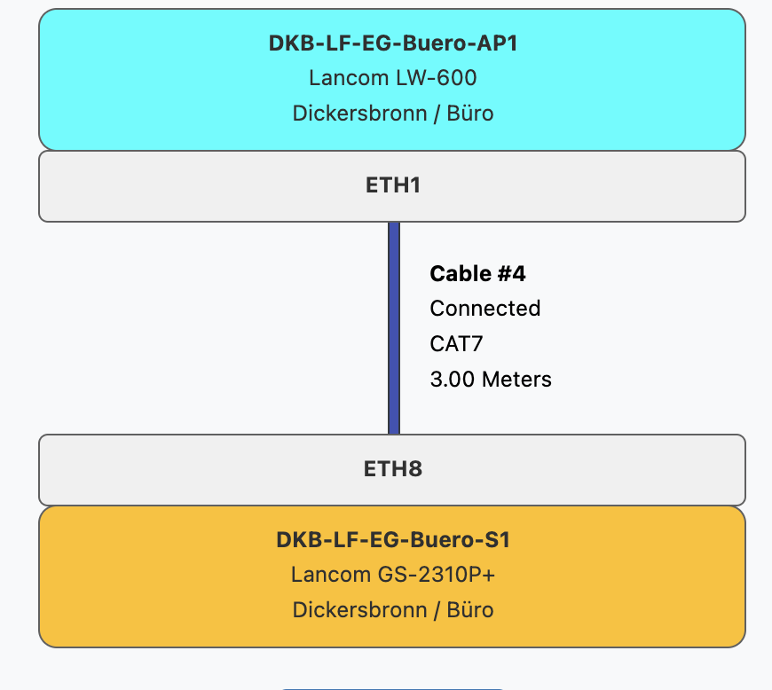
I have in one room a switch, under this switch are, instead of a patch panel two network sockets attached to the wall, once the supply line to the core switch and once to another switch in another room, see picture.
When I now connect the two switches in Netbox, currently all think these are connected directly and not via the network socket.
Thanks.
Beta Was this translation helpful? Give feedback.
All reactions