electronic switch to control battery from Espruino GPIO #1607
Replies: 9 comments
-
|
Posted at 2016-08-17 by @gfwilliams Well, a GPIO line should really be good enough. Could it perhaps be a timing issue, as displays often need a few msec after being powered on before they're ready? You've also got to be careful that you don't power them up via their IO lines first (eg, if you init SPI beforehand) I think you actually want a P channel mosfet (which pull the voltage 'up' to 3.3v when the gate is pulled down) - but hopefully you don't need that and it's some other problem :) |
Beta Was this translation helpful? Give feedback.
-
|
Posted at 2016-08-17 by DrAzzy Is that the correct connection for a coin cell? Shouldn't a coin cell that will never go above 3.3v be connected to the 3.3v rail directly, to spare you from the regulator dropout? |
Beta Was this translation helpful? Give feedback.
-
|
Posted at 2016-08-17 by @gfwilliams
Good point - if you're sure it'll never go above 3.3, and you're not planning on having it in while USB is plugged in then yes - and it should save you 0.3v or so. |
Beta Was this translation helpful? Give feedback.
-
|
Posted at 2016-08-17 by @allObjects ...I'm sure you have looked at GPS powered by Espruino pin(s). |
Beta Was this translation helpful? Give feedback.
-
|
Posted at 2016-08-17 by MichaelPralow
checked that and upped the waiting times, had no success
thanks for the tip, changed the code
the coin cell shall power the Espruino Pico and the display as well, i am not sure about this 3.3v rail, what do you mean?
thx for the link, i am not sure that is the problem here, as one pin should be more than enough maybe the lot of pins draw too much current so the direct connection to VBAT is needed? is there enough voltage? ok i used a multimeter - was my first time btw, it seems more of a problem with voltage, the whole circuit is around 2,3v, but the typical operation voltage for the display goes from min. 2,4v to 3,3v |
Beta Was this translation helpful? Give feedback.
-
|
Posted at 2016-08-17 by @allObjects You have the power suply pin and you have the control/signal/data exchange pins. Latter are not a power draw issue as long as you do not add extra load - such as 'low' value resistors from display output pins, for example, MISO, to ground. @gfwilliams thus mentioned that the control lines - (output) pins from Espruino to connected to display - should not power the display while power is off. Therfore, when powering up espruino and initializing AND before powering down the display,, these pins have all to be set input float ("input"). Only AFTER display is powered up, pins and communication - SPI - can be initialized and set. Note that for proper working, signal lines do not need to go up to voltage supplied to display, but (certainly) should not be higher (otherwise they will power the display in one way or the other, or at least, try to...). The signal lines have only to reach a high or low as input specs with given supply voltage are specified, and that's true for both Espruino and display. |
Beta Was this translation helpful? Give feedback.
-
|
Posted at 2016-08-18 by @gfwilliams
Usually, you have 5v coming in from USB... That goes through a voltage regulator which brings it down to 3.3v. The problem is the voltage regulator 'loses' a bit of voltage, so say you have input voltage V, the voltage coming out is either So if you feed it from 3v, the 3.3v rail only gets 2.7v. To fix that, you can just cut out the voltage regulator and connect the 3v battery straight to the 3.3v rail. What type of display is it? Could it be that the display is actually working, but the contrast is different because it's running off lower voltage? |
Beta Was this translation helpful? Give feedback.
-
|
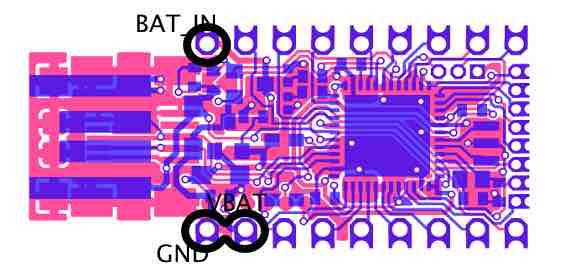
Posted at 2016-08-18 by MichaelPralow i thought when using the VBAT pin i get the (raw) battery voltage from BAT_IN? i uploaded a picture to show what i mean
thanks, that explained some weird behaviour anyways it seems i found the cause for the root problem, i am using an e-paper display (SSD1606 controller with GDE021A1 display), but in a convenient ready-to-use module, which includes all the needed stuff (capacitors, etc.) for a proper working SSD1606 controller well this module draws up to 25 mA current (at least that is what my multimeter showed me), it really works perfectly when driven by VBAT (e.g. CR2032 or 2x AA eneloops) ok now i could use more pins like @allObjects proposed, but i will need a lot of pins for the final project (DCF77, e-paper display, maybe bluetooth BLE), i will find out if that is possible with one CR2032 :-) the topic for electronic switches seems to be quite complicated so i take my time and start learning, i will try it with a mosfetAttachments: |
Beta Was this translation helpful? Give feedback.
-
|
Posted at 2016-08-19 by @gfwilliams
Yes. If you connect the battery to BAT_IN, that voltage appears on I'd definitely suggest a P channel MOSFET. Things get tricky when you have voltages above 3.3v (because the Pico's outputs only do 3.3v), but because you're running everything at 3.3v it's just a matter of connecting one between 3.3v, the Pico, and the display. Have you seen http://www.espruino.com/mosfets ? |
Beta Was this translation helpful? Give feedback.
Uh oh!
There was an error while loading. Please reload this page.
-
Posted at 2016-08-17 by MichaelPralow
I want to control the power for a display with using an electronic switch.
what i know / want to do:
so far i am just searching and learning (i have absolutely no idea of electronics and it is a wide field for a beginner) and as far as i understand a NPN mosfet would fit here, the big question is - which one should i choose or is there a better way to switch the power for the display?
Beta Was this translation helpful? Give feedback.
All reactions