LED and digitalPulse/digitalWrite/analogWrite and *read #323
Replies: 6 comments
-
|
Posted at 2014-11-08 by DrAzzy Edit out wrong answer |
Beta Was this translation helpful? Give feedback.
-
|
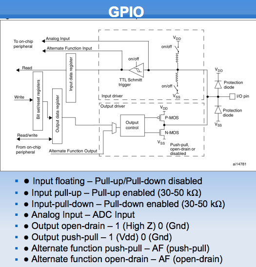
Posted at 2014-11-08 by @allObjects Take a look at the pinMode() function. When pin mode is set to automatic - by executing pinMode( pin ) w/ no 2nd argument - before read or write operation, then read and write defines at the same time the wether the pin is input or output pin. The pin is not a register that you set or unset and then read back what you have set (or unset). What you get back depends on how the pin is setup in detail. For simplicity - when in auto mode - write sets the pin in output mode - and will apply power (make the pin sink or source), read sets the pin in input mode. After ESPRUINO is started, you can ask the mode of a pin with getPinMode(pin). You will notice that different pins are set to different modes. The A13, A14, and A15 pins - respective LED1 (red), LED2 (green), and LED3 (blue) - pins are set to 'output' - as you can verify with getPinMode(A13) - and it is in automatic mode. Executing digitalRead(A13) makes it an input. If LED1 was off before the read, you get 0 back, and when LED1 was on, you get 1; but notice that when it was on, the read will making it to go off, because the pin is not powered anymore. When pin mode is with second argument - pinMode(pin,mode) with mode a string that is either 'input', 'input_pullup', 'input_pulldown', 'output', 'opendrain', 'af_output' or 'af_opendrain' - the mode is fixed set, and digitalRead(), analogRead(), digitalWrite(), and analogWrite() do not change the input/output mode. Interesting though is, than when you do a digitalWrite(A13,1) while A13 is in fix input mode ('input', 'input_pullup', 'input_pulldown') and then do an 'output', LED1 goes on... because A13 output register is now connected with pin... Returning back to automatic mode, execute a pinMode(pin) - no 2nd argument. About open and pulled-up/down input:
Attached schematics may help a bit. Google found it for me and with a bit poking around in the Web, I came across these http://www.gahum.com/index.php?title=EDUCATIONAL&subtitle=PROGRAMMING, http://112.210.106.111/ECE423/ links... which ended up on the .pdf w/ the schematics - http://112.210.106.111/ECE423/ECE423N_DAY5.pdf?Attachments: |
Beta Was this translation helpful? Give feedback.
-
|
Posted at 2014-11-08 by favo @drazzy, nope, it is in ms. |
Beta Was this translation helpful? Give feedback.
-
|
Posted at 2014-11-08 by DrAzzy Sorry, my bad. I just got up, and was getting it confused with the other time functions. |
Beta Was this translation helpful? Give feedback.
-
|
Posted at 2014-11-09 by @allObjects @favo - I updated previous post... because I'd left some stuff out... I hope that after having made it too simple the first time, the second edition is not adding (too much) confusion. STM32F103's GPIOs are extremely versatile, hence GPIO configuration and understanding of GPIO behavior IS a challenging... there are quite many publications and forum posts and... out there, in addition to ST's chip manual. Google it with https://www.google.com/search?q=GPIO+STM32F103 |
Beta Was this translation helpful? Give feedback.
-
|
Posted at 2014-11-09 by favo wow, thank you @allObjects ! I will try to read more about it, for now its little more confusing but I'm coming from pure software development and need to think a little differently about things like this, I'll try to get it all into my head ;-) For now working with pulse & write/read got really easy, I especially love how easily you can queue several pulse calls and your hint to |
Beta Was this translation helpful? Give feedback.

Uh oh!
There was an error while loading. Please reload this page.
-
Posted at 2014-11-08 by favo
Hi there!
I'm new to the whole topic and I've received my first espruino this week and wanted to play around with it on this weekend. Most things work great out of the box but I am struggling a little with understanding the read/write functions.
I'm trying to light an LED for only 100ms by entering
digitalPulse(C8,1,100);, but .. the LED stays on indefinite. When reading the current status withdigitalRead(C8);it turns off again. In additiondigitalReadalways returns 1.So I tried the same with the analog functions by entering
analogWrite(A0,1);which turns it on and withanalogWrite(A0,0);I can turn it off. But what puzzles me, is when I runanalogRead(A0);it also turns it off.My question therefor is: Why do the reading functions turn it off? I was expecting to receive what I've written / the current status of the pin.
Thanks for taking time to read and answer! :)
Mario
Beta Was this translation helpful? Give feedback.
All reactions