MDBT42Q and 5v water pump #3536
Replies: 12 comments
-
|
Posted at 2020-10-20 by @gfwilliams Hi - that all looks great. Are yo using the exact same FET? I guess some of them may have different pinouts. And what happens? Nothing at all? |
Beta Was this translation helpful? Give feedback.
-
|
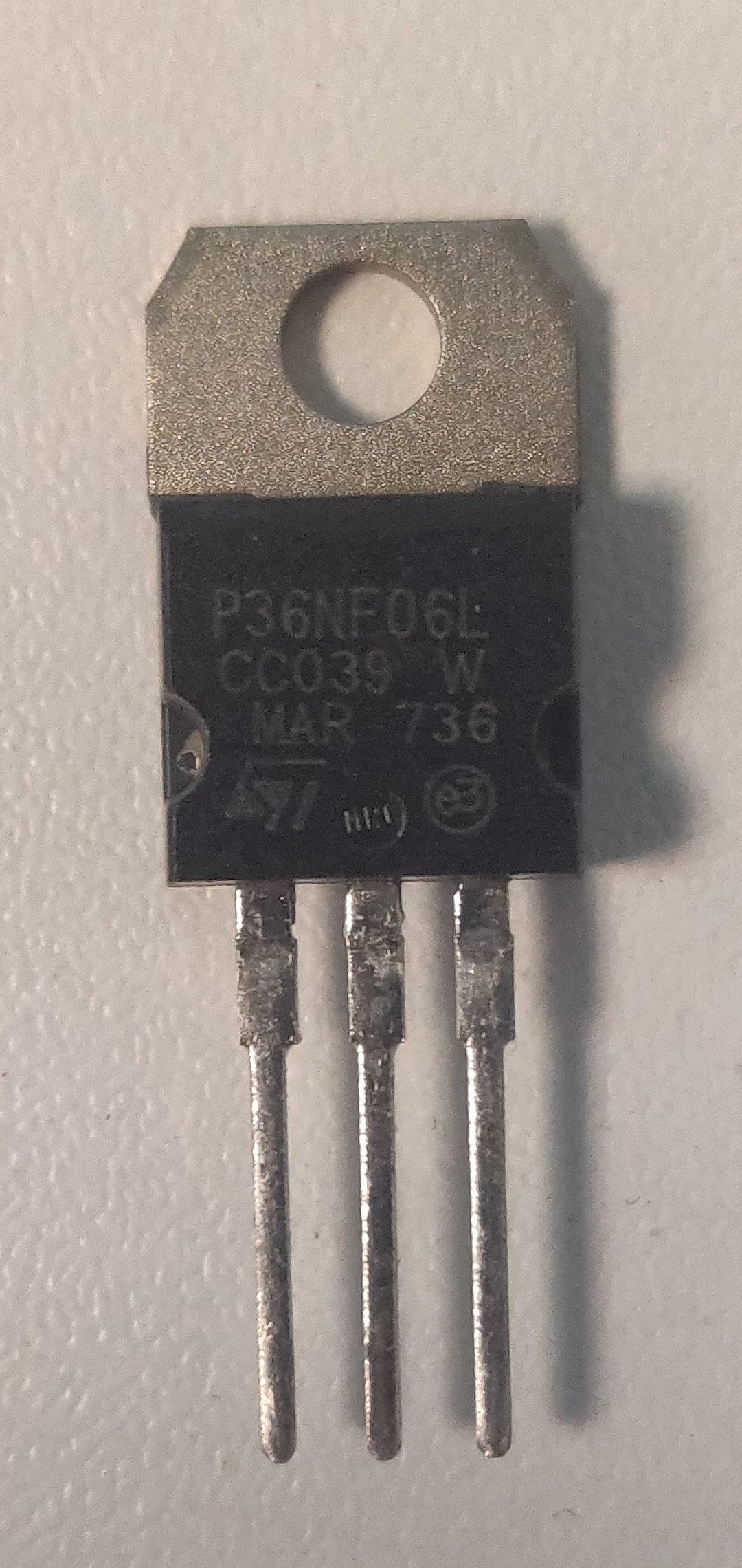
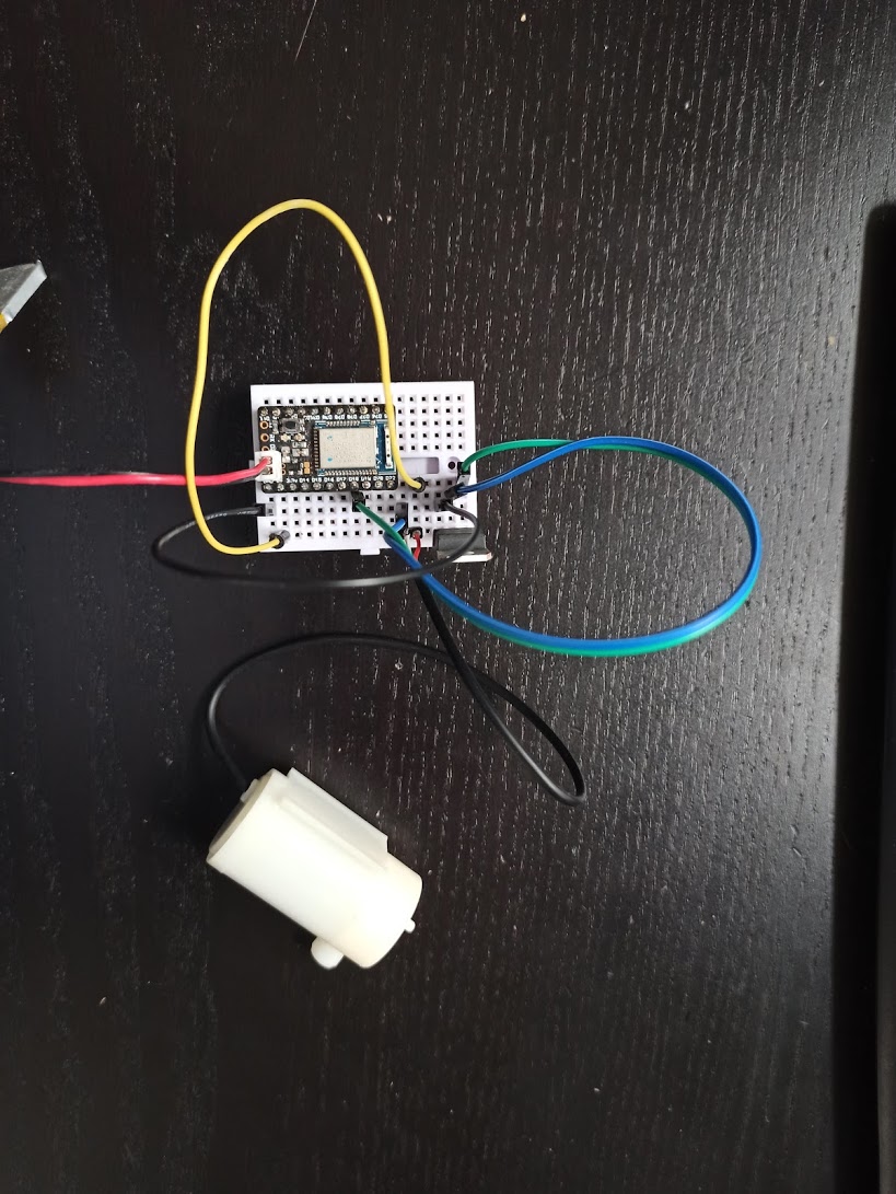
Posted at 2020-10-20 by michael_101 Hi Gordon, Thank you for your quick reply. I'm using this FET. Nothing happens. If I connect it directly to the board +/- 5v it works fine so no problem with the pump it self.Attachments: |
Beta Was this translation helpful? Give feedback.
-
|
Posted at 2020-10-20 by @gfwilliams Honestly what you've got there looks perfect. And doing Is it possible you could have wired the FET up wrong previously and blown it up? I just wired up your circuit on breakboard, with that exact P36NF06L FET and the exact same water pump, running off a ~4v LiPo battey, and it works great. |
Beta Was this translation helpful? Give feedback.
-
|
Posted at 2020-10-20 by michael_101 Hi, I did digitalWrite(D18, 1), now I tried D18.set() and D18.reset() same result. I have 5 pcs of those new FETs I'll be surprised if they are all broken, what is the proper way to check/test them with multimeter? Thank you. |
Beta Was this translation helpful? Give feedback.
-
|
Posted at 2020-10-20 by michael_101 This is the test I did on FET Video with length of 44 seconds |
Beta Was this translation helpful? Give feedback.
-
|
Posted at 2020-10-21 by @gfwilliams Hi - sorry, when I meant check the voltages I meant to check the voltages with it all plugged in to the MDBT42Q.... So to see if the voltage from D18 was getting to it for instance. It could just be a dodgy connection on the breadboard. As I say I have wired up the circuit exactly as you have done to test, and it works great for me.Attachments: |
Beta Was this translation helpful? Give feedback.
-
|
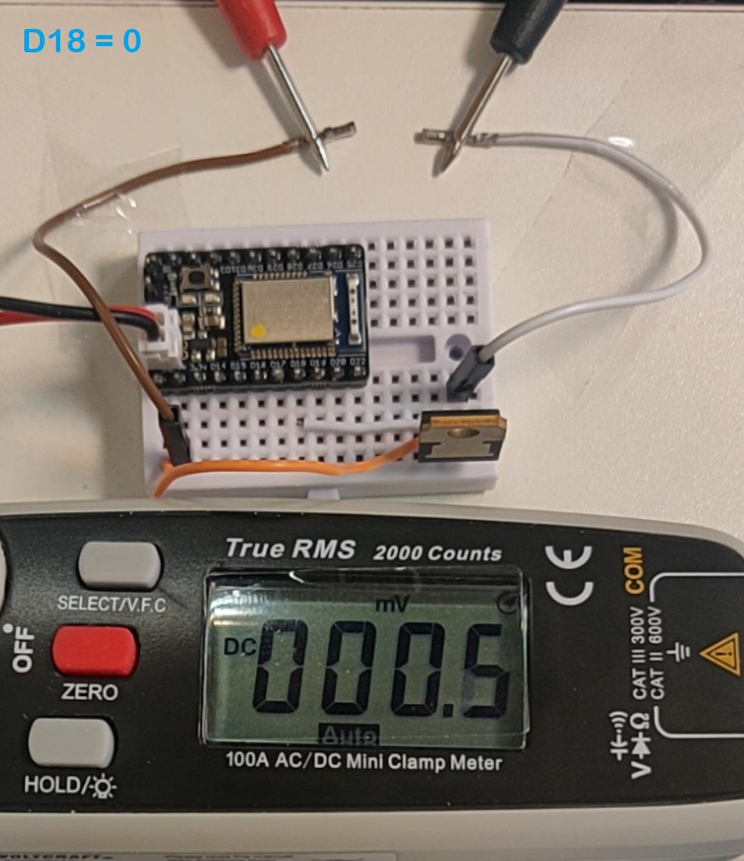
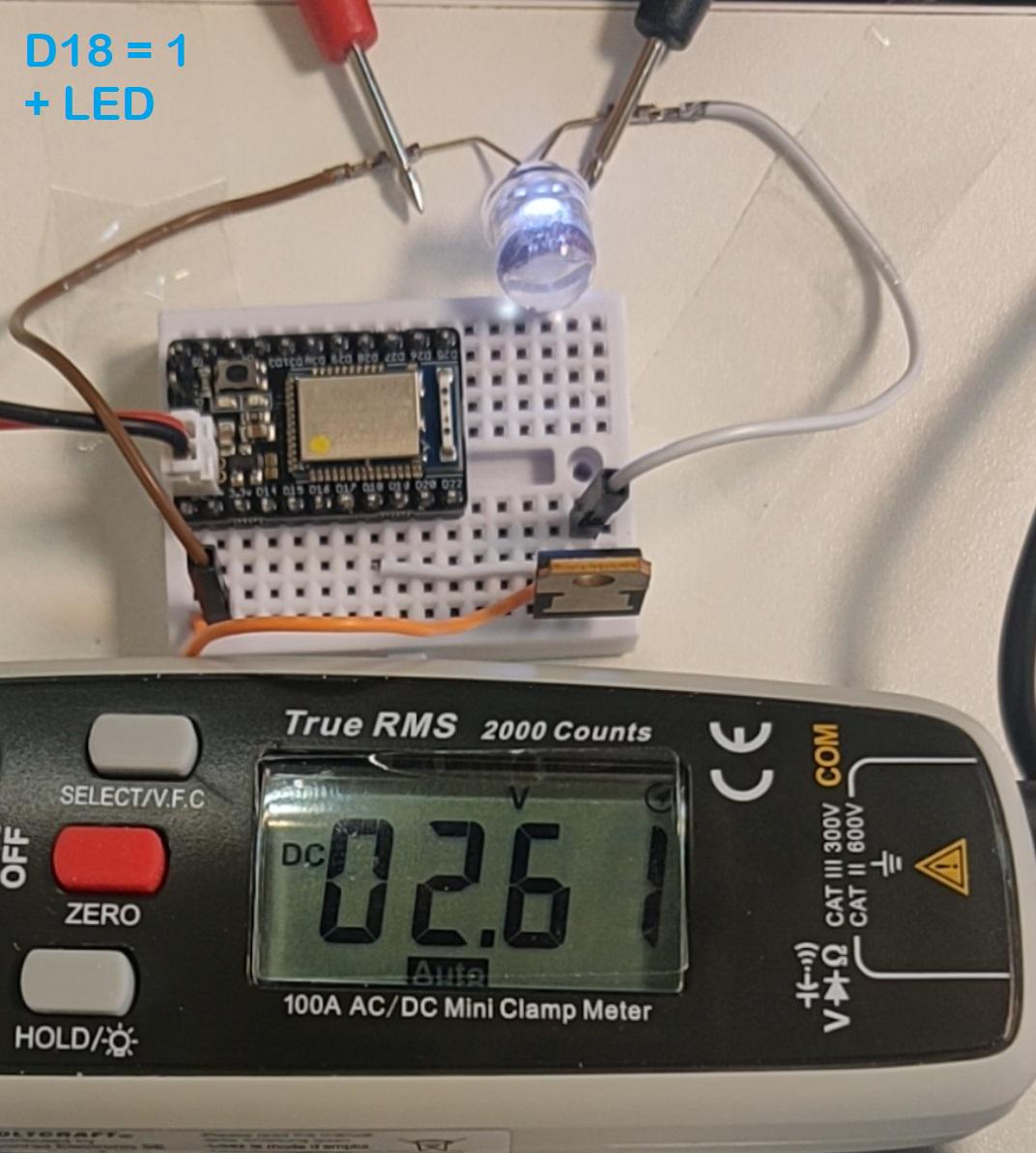
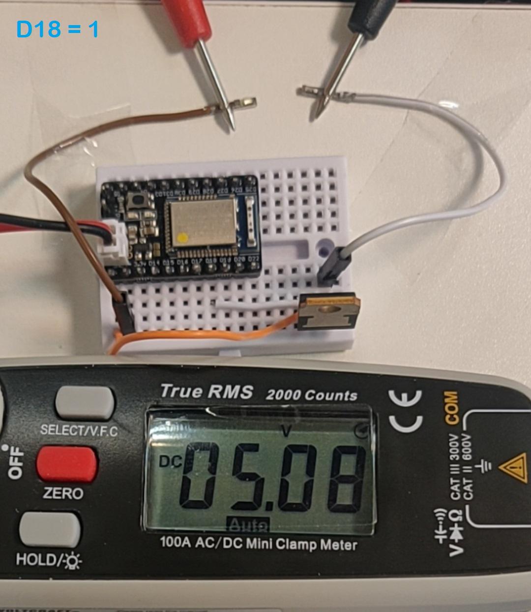
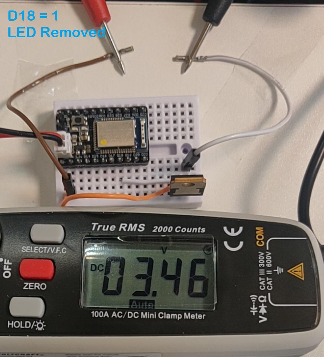
Posted at 2020-10-21 by michael_101 Hi, This is what happens every on/off of D18 D18 = 0 - 0v Thank you.Attachments: |
Beta Was this translation helpful? Give feedback.
-
|
Posted at 2020-10-21 by @allObjects @michael_101 I'm not sure what you measure is what @gfwilliams is asking for. Have D18 connected to the Gate of the MOS FET and pump con connected. Then with for both states -
Then power off everything (disconnect from power source) and replace wire from FET Drain to Pump with Multimeter with setting for Current measurement. Then power all on and measure the current with With breadboard contacts can be flaky. Therefore you measure at the FET Gain pin and compare what you measure at the MDBT42Q Pin 18. To catch eventual contact issues with the wiring, use also other points on the bread board. Of course you can also measure MDBT42Q Breakout Pin 18 output voltage with Pin 18 not connected. Your Multimeter has an auto setting which will not always measure what you want to measure. Comments to your measurements so far... they look good to me... may be with one exception: what is the difference between picture 2 and 3? Also, can you show 'the other side' of the FET? ...to see the orange, white and eventual other connections that happen?... (you can also just bend down the FET so the pins and wirings and breadboard points become visible and update the pics. Btw, 'never ever' run an LED directly... use a resistor 'in Series'. A forward bias voltage lower than the source (5.08V) is like a shortcut of the source (2.61V) and if the source (and eventual controlling circuit - FET) is strong enough it will heat and eventually burn up the LED, or, if the controlling circuit - FET - is 'weaker' than the LED, it will heat and eventually burn up. |
Beta Was this translation helpful? Give feedback.
-
|
Posted at 2020-10-22 by @gfwilliams So by the look of it you're saying that if you connect a LED across the wires, you can control and LED using D18 as expected? Just not the pump? Also as @allObjects says, what happened in the final picture |
Beta Was this translation helpful? Give feedback.
-
|
Posted at 2020-11-16 by michael_101 Hi, Thank you @gfwilliams and @allObjects for your detailed answers I learned a lot from them and sorry for the delay. I got it to work, apparently all 5 FETs I had were not good. I did the tests as you asked me with this results: D18=1:
D18=0:
About the current measurement from FET Drain:
So I bought 25 new same FETs and I did the same test (20% of them were not good too). Thanks again. |
Beta Was this translation helpful? Give feedback.
-
|
Posted at 2020-11-16 by parasquid Wow. That's a really bad failure rate. I stopped buying my stuff from aliexpress and started using digikey for bulk purchases (since they do free shipping for over $50) or element14 for smaller batches (which is slightly more expensive per item but free shipping all the way). |
Beta Was this translation helpful? Give feedback.
-
|
Posted at 2020-11-17 by @gfwilliams Wow, yes, that is bad. Where did you get the FETs from? People do actually counterfeit electronic components sometimes, and it's possible that you actually got some counterfeit parts. It may be that the FETs do work, but they just need higher voltages. I'd chosen the P36NF06L for some examples because it's one of only a few 'big' FETs that conducts a useful amount of power at 3.3v gate voltage - but it's possible someone repackaged some less good FETs in a P36NF06L package! |
Beta Was this translation helpful? Give feedback.
Uh oh!
There was an error while loading. Please reload this page.
-
Posted at 2020-10-20 by michael_101
Hi,
I'm trying to do the same thing as here:
https://www.youtube.com/watch?v=epEGN-7GsPs&t=312s
The only difference is that I'm using MDBT42Q and it's +/- bat pins with 5v and not an external power source. (without a diode for now)
The switch pin in my case is D18. (See attachment photo)
What could be the problem?
Thank you,
Michael.
Attachments:
Beta Was this translation helpful? Give feedback.
All reactions