What volts can I supply the VBAT pin with? #5369
Replies: 1 comment
-
|
Posted at 2015-04-29 by alexanderbrevig VBAT would be the pin to connect V+ (3.5-16v) indeed. For some reason, your question got me uncertain - but I don't see it being any other way. Posted at 2015-04-29 by @allObjects We are talking BAT_IN on schematic, which on the board is the pin next to B15 - marked Bat - and the pad on the back side - marked + - (where a battery connector can be mounted). The markngs on the back are not very conclusive / matching with the schematic... rather confusing... On the other hand, only savvy poeple look at the schematics, regulars just look at the markings... and schematic's BAT_IN is board's marked Bat and + sign - no ambiguity on the board itself. According to the schematics / the board routing, USB power feeds the regulator over a diode and the BAT(tery)_IN - Bat pin next to B15 - over the P FET. The regulator feeding point is connected to the 0.1" and 0.05" (V)BAT pins - marked VCC - grouped with the 0.1" and 0.05" GND and 3.3V pins. I do not know the behavior when connecting a battery to (V)Bat:
@AlexanderBrevig concludes that the (V)Bat is the place to connect a bat from 3.5..16V... and see no issues when not connected to USB power/USB connector. When connected to USB Power, it can become an issue when the (V)Bat conneted battery starts to draw current (Battery delivers less than 4.7V). With other words, BAT_IN is safe for sure, and V(BAT) is safe as long there is no USB POWER connected. Therefore, when you do not plug it into a powered USB porte (kond of an oxymoron by the definition of the USB port...) you can use either. Putting the FET/B0 solder jumper in, makes it a different ball game. Posted at 2015-04-29 by DrAzzy The PFET prevents the USB power from trying to charge the battery when its connected to BAT_IN, but not when it's on VBAT Posted at 2015-04-29 by @gfwilliams Yes, as others have said - if you have a battery, connect it between You're totally fine with 3.5-16v on there, but you should be aware that when you do that, Posted at 2015-04-29 by DavidSchoen Hi All, Thanks for all the answers. I've had a go at following all of the above and also spent more time following traces, probing points on the board, etc, my understanding is now as follows:
I think my original question was doubly confusing as I'd confused Another question comes up though if I need a few 3.3V devices - the regulators according to the power section appear to be MCP1703T-3302E-CB which is rated up to 250mA - is this the correct limit for the version on the board and are there any other limits that will cause a problem first? Would it make sense to put as many devices on the 5V regulator ( I don't think I will come close to the limit for anything I'm currently trying to solve (but I will actually test mA on each device individually now), but I'd just like to know what the best approach would be (short of introducing another regulator / external voltage follower / etc). Cheers, Posted at 2015-04-29 by @gfwilliams
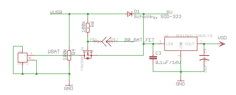
It doesn't I'm afraid (there's no 5v regulator) - the VBAT pin is battery or USB volts, so you need to be careful there. There's actually the circuit diagram of the power supply here: http://www.espruino.com/Pico Afaik the MCP1703T will handle 400mA peaks, but only 250mA constantly (even at that it's likely to get toasty regulating down from 16v though). I think it depends what you're doing - if you have devices that will run from whatever battery volts is then I'd run them off battery volts, but if you're running some very heavy duty 3.3v stuff then I'd go for an external regulator. However, the obvious 3.3v regulators have a ~4mA quiescent current (so drawn all the time), so if you're going after power consumption I'd avoid them. A few regulators have an enable pin though, which could be very useful - allowing you to actually turn off stuff that isn't needed. Posted at 2015-04-29 by DrAzzy @gfwilliams - according to the datasheet, the MCP1703T is not as good as you're suggesting... The limit is power dissipation from the SOT-23 package. See pages 13 and 14, about the power dissipation calculations... Running off USB, taking 4.7v, bringing it down to 3.3 (ie, dropping 1.4v), well, let's do the example at 25C ambient... SOT-23A (336.0°C/Watt = RθJA) 300mW / 1.4v = 213 mA So even just running off USB, it's not rated for 250mA continuous... Posted at 2015-04-29 by @gfwilliams Ahh - thanks. Missed that... I figured 250mA was very optimistic at 16v, but it's interesting it can't hit that even at under 5v. Posted at 2015-04-29 by @allObjects
@davidschoen - visualization provides understanding... (and matching schematics to board). That's what I had done to understand what's going on. Attachments: Posted at 2015-04-29 by DavidSchoen
Given this is the only big thing you thought I got wrong, I had enough confidence to wire up 10V to the I've had a look at that power diagram a couple of times, but without knowing more about how it worked I couldn't really get much out of it because the pins on it are Given the little business card that comes with the kit, the board itself and the schematics all have different names for these pins - do you think that a section could be added to that page clarifying which pins have changed names over time and what those various names are? Posted at 2015-04-29 by DavidSchoen Thanks +allObjects, that's way more illustrative! Do you know what the device between the GATE/SRC/DRN pads is? I had assumed that would be a regulator for 16V -> 5V (and hadn't yet been confident enough to supply > 3.7V to Posted at 2015-04-29 by DrAzzy Yeah - we definitely need to unify the nomenclature for power pins... See also http://forum.espruino.com/conversations/266857/ for more discussion of this with an eye towards the silkscreen on the second run Picos. Posted at 2015-04-30 by @gfwilliams Yes, sorry about that, it's a bit of a mess - I didn't realise quite how bad! Bit busy today but I'll make sure I update the
Yes, it's a PFET (Q1 in the circuit). Basically it turns itself on when USB is disconnected, which means you can then run off a battery without any voltage drop (which you'd get if you just used a diode). Attachments: Posted at 2015-05-01 by DavidSchoen Awesome, thanks again +Gordon (especially for taking the time to humour me about figuring out what the PFET was) :) Posted at 2015-05-01 by @gfwilliams No problem - there's a bunch of documentation, and often I only know that bits of it are inadequate when someone tells me :) Posted at 2016-05-17 by Cale I know this is an old thread and I just had a quick question that is related. For a battery greater than 12 volts (less than 16 volts) my PICO disconnects from the Web IDE. Could not find this covered anywhere. Posted at 2016-05-18 by DrAzzy Is it shutting itself down because youre putting a load on it and it's oberheating? Posted at 2016-05-18 by Cale I thought that so I unplugged it from the board so that it was completely solo and it still disconnected. Posted at 2016-05-18 by @gfwilliams So even though it's just on it's own, it's no longer working? How did you connect it to the battery? If you use VBAT then you should be fine. If you used the USB connector it's going to have broken one of the inputs - USB is only meant for 5v, and there's an IO pin connected to it so the Pico can tell if it's powered from USB or not. If it's happened there's still a way to get USB working, but it's not perfect. The other option is might you have had something connected to an input that was also 12v or more? Like a PNP transistor connected to 12v? While you can power the Pico from a high voltage, it's GPIOs will only handle 5v. Posted at 2016-05-18 by Cale I am using a power supply and it is connected through the BAT_IN. Just tested another one. The LED starts blinking (it shouldn't be) when the power supply is connected. Posted at 2016-05-19 by @gfwilliams Do you have your own software on the board, or is it a plain board that you're just applying power to? Posted at 2016-05-19 by Cale Its a PICO with 1v85. Other than that nothing is on it when I tested this Posted at 2016-05-19 by Cale I made this little video to show what I am talking about. Posted at 2016-05-20 by @gfwilliams Thanks for the video - that's really helpful. So if you write: to the board, then type I'm just wondering if this could be some kind of strange grounding issue (as maybe both the laptop and power supply are powered off the mains)... I've got a Pico doing plant watering that I left connected to a car battery (so 13v-ish) all summer, and I never had issues even when plugging in a laptop. Other thing is - did you do the Pico FET tutorial? Any chance you left the solder jumper on the back soldered up? Even if not, if you have some contact cleaning fluid (isopropyl alcohol?) you could rub over the rear of the board, making sure the two solder jumpers are cleaned. Potentially some salt from fingers could have got on it, and that might be causing problems for the Pico. Posted at 2016-05-24 by Cale I have not done the FET tutorial. This is consistent on every PICO I have tried thus far. Its a little concerning because the current project is similar to what your doing. I am actually creating a wireless sprinkler control system where I have solar panels built into the in ground sprinkler boxes connected to a 12 volt battery. I can add a lm7810 to the circuitry but was hoping to get away without having to. I did try cleaning the back up with alcohol and still no change. https://goo.gl/photos/qfNoU1xSMsBseRoM9 Posted at 2016-05-24 by @gfwilliams I just tried it here and got the same disconnection as you (although I can still program the board with power applied). Honestly I'm a bit confused about what's going on. The power supply circuit is here: http://www.espruino.com/Pico Looking at VBat, it's doing what we'd expect, and the 3.3v pin still seems stable at 3.3v - the regulator is rated for 16v normal (and 18v max). I guess potentially the voltage regulator might somehow shut off when the input voltage rises suddenly? But once power is applied, I can write some code, unplug and replug USB, and everything stays working fine... So in your case as well (sprinkler where power would stay connected) it should be ok? But that doesn't explain why you can't reconnect? Are you using Windows? I can't tell from the video but it seems likely. I wonder whether the issue is actually because of a Chrome bug. I know if you just unplug a USB device while Chrome is connected, when you reconnect you can get a problem like you're experiencing where you can't send or receive data. It could be that the disconnect when power is applied is causing that to happen. If you disconnect the Pico from USB, shut down the Web IDE and start it again, it might work next time you connect. I guess the way to stop it is to start the Pico powered off 14v, and to then connect USB and keep it running off the 14v power supply - that should work. Posted at 2016-05-24 by Cale Yeah I am doing that now and its very unreliable for some reason. Very few times have I been able to reconnect. Never over 14 volts have I been able to. I am using the Dell Chromebook. I tried it on my windows computer and nothing changed. Posted at 2016-05-24 by DrAzzy When it's not working, is Vcc actually at 3.3v? Measure it... If you have a scope, put the scope on it. There's no black magic, and the only connection between the regulator and the Pico is through power and ground - so what's it doing to the power? Posted at 2016-07-07 by Cale So I checked it over extensively and here is where I am at. I have a NRF905 connected exactly as follows: When I have the PICO connected to the NRF905 with the computer powering everything works fine. When it is connected to the the battery without the NRF905 I can still talk to it with the computer. When connected with the battery and NRF905 then all connection is lost and am unable to reconnect. The pico led blinks very fast. The pins seem to read as follows (connected to computer only, or connected to battery without NRF905): With the battery they are similar but seem to be resetting over and over. GND is 0v, VBAT is 13V, VDD is 3.3v, B3 is floating, B4 is floating, B5-A8 are 0v. I do have an oscilloscope but its currently not working properly..... And not sure where to even begin even if it were working...... Posted at 2016-07-08 by Cale So I actually tore into my oscilloscope and found that a wire on the horizontal deflection plate was disconnected. Anyways, I can say that when less than about 9.5 volts the pico keeps working. 10 volts will cause a slow resetting of the pico while at 13 volts it will reset quite a bit faster. Also at 10 volts it takes a few seconds before it started resetting where as 13 volts it's immediate. The USB side of the Schottky diode appears to be pulsing and the BAT side is steady. So at BAT 12 volts the USB side is jumping between around 3.3 volts and 8 volts. FET and B0 are not connected and when checked for resistance do not register at all. The supply side of the regulator is steady at BAT Volts and GND is steady 0v where 3.3 pulses to 0v Posted at 2016-07-08 by @gfwilliams I'm not really sure what's up - I asked around and all we could think of is that the diode breaks down with a certain reverse voltage. Which revision board do you have? I did change the diode for a better one on the rev 1.4. Now, when we checked, the reverse voltage was within the allowed limits - 30v or so, but I wonder whether if the diode has been stressed - especially on the 1v3 (even a momentary short) - then it might break down at a lower voltage than rated. If you're ok just powering it off 12v, how about just removing that diode? It should be relatively easy to take off (or just lift one side) with a soldering iron, and should totally fix your problems - although after that you'd have to make sure the Pico was powered externally to program it. Sorry about that, but it's about the only thing I can think of at the moment. Posted at 2016-07-08 by @gfwilliams Just to add, if USB is jumping to 8v that'll definitely be causing the reset - and you should try and avoid doing anything that makes that happen as it'll eventually kill the GPIO line attached to it, which will stop you from being able to connect over USB. But that does mean that the only thing that could be causing the voltage is that diode... I just checked and the rev 1.3 has a 1PS76SB40, which has a reverse voltage of 40v so should also be fine. Posted at 2016-07-08 by Cale So this Pico I am currently using is 1.4. And remember this does NOT happen when the nrf905 is NOT connected. So i suspect it's something to do with current? Posted at 2016-07-08 by @gfwilliams How much power does the nRF905 draw? Maybe you could try putting a capacitor across the power lines to it. Is anything hot on the Pico? The voltage regulator has over-temperature protection There's also a polyfuse for overcurrent - is it possible that you connected the nRF905 to the 'Vout' pin of the Pico - which would be 13v? That would then massively over-volt the nRF905, which would probably put high voltages on the IO lines, which would go back into the Pico's STM32 and might also raise the voltage on the USB line. Finally the polyfuse would trip and cut the voltage - but it's self-resetting so it would just keep doing it over and over. |

Beta Was this translation helpful? Give feedback.
Uh oh!
There was an error while loading. Please reload this page.
-
Posted at 2015-04-29 by DavidSchoen
Hi,
This may be kinda dumb, but I'd rather ask a dumb question before I break my Pico :)
On the Pico page (http://www.espruino.com/Pico) it talks about the voltage regulator accepting between 3.5-16v and the board being happy to run on a 3.7v Lithium cell - can I use the VBAT pin for either or if I wanted to supply a higher voltage should I be supplying it via some other pin?
So far I've been running a regulated buck converter set on 5V through a USB plug I've wired up "just in case", but I'm wondering if I can just chuck a less well regulated supply straight at VBAT?
Cheers,
Dave
Beta Was this translation helpful? Give feedback.
All reactions