I2C timeout with OLED display on Pico #5424
Replies: 1 comment
-
|
Posted at 2015-04-24 by @gfwilliams I2C timeout basically means at the lowest level, the Pico can't get a response off the display at the given address. So it's almost certainly some wiring issue (or a broken display) Are you connecting to Are you using the 0.1" pins, or the small connector? It looks like the 0.1" pins might not be connected to the same things as the small connector (so might not have I2C on them). Also, are you sure SDA and SCL aren't mixed up? I always end up doing that :) Posted at 2015-04-24 by DrAzzy Do you have a pullup resistor between Vcc and SDA, Vcc and SCL? I have actually also never had any luck making those displays work, though I've only tried two, and both are suspect. One I'm not sure I got into I2C mode (it had pins like a centipede for a million interfaces), and the other one doesn't have the voltage regulator, and I accidentally applied 5v to it instead of 3.3 (mine was spec'ed 2.6-3.3), so it may be dead. Posted at 2015-04-24 by @yerpj @gfwilliams: I tried to power the display through the VBAT and 3V3 (right next to the GND pin). @drazzy: I have 10k pull-ups on both SDA and SCL. I although tried to put 4k7 resistors, without any better results. The display is rated between 3V3 and 5V. In my case, I could not damage it (or should I say , damage them, because I tried each of my 3 displays) Weird, isn't it? Posted at 2015-04-24 by Pinnchus Try with this examples http://forum.arduino.cc/index.php?topic=159851.0 Posted at 2015-04-24 by @gfwilliams Yes, it's really strange. Just looked at the datasheet: http://www.embeddedadventures.com/datasheets/SSD1306-Revision%201.1%20(Charge%20Pump).pdf See
I actually have a board that's like that - this one: http://www.embeddedadventures.com/oled_display_128x64_OLED-12864-WHITE.html So I'll see if I can come up with a 3 wire SPI version - just shorting those pins might be easier though! Posted at 2015-04-24 by @yerpj @gfwilliams: Gordon, you got the answer! "Luckily, there is an easy fix ! Just put a solder bridge between pins 19 and 20 of the flat cable going to the OLED and everything works :-)" Thank you Gordon! Just a bit of further information: For those who bought their OLED displays on Hobbyking (the ones that are manufactured by hexTronik). You should not have to patch the reset circuit, it already exists on the PCB (R3 and C10, next to pin 14). If someone wants to have a look at the patch, you'll find nice pictures of the patch here: hallard/ArduiPi_SSD1306#1 Attachments: Posted at 2015-04-24 by DrAzzy Good find, I'll look into that on mine... I've got an SPI and I2C version (the latter being possibly fried) sitting on my desk. Posted at 2015-04-29 by DrAzzy Hmm, I2C version now doesn't complain (now that I've shorted pins 19 and 20, but it also doesn't work - screen remains dark. Mine is a Heltek (hell-tech?) Posted at 2015-04-29 by @gfwilliams Could be it needs 5v? It seems like the power supply for the OLEDs is pretty flaky on some of them. The fact that it responds to I2C is good though - at least the driver chip is active. Posted at 2015-05-04 by Perka DrAzzy, I have a Heltec 128x64 I2C screen that I have been using with Arduino. It took me some time to get it to work, because it didn't send and ACK back that most drivers expected. Could this be a problem here? I haven't tested it with my Espruino Pico yet... Posted at 2015-05-04 by Spocki I have the Heltec, too. Could never get them to work (changed 3V3 and 5V, with or without pullups). Posted at 2015-05-05 by @gfwilliams Did you both try shorting pins 19-20 together? That's most likely the problem with these boards. Potentially we could come up with a non-I2C driver that would still work on those screens I guess... it shouldn't be too difficult. Posted at 2015-05-06 by Perka Now I have tried my Heltecs and I cant get them to work. Shorted pins 19-20 on one of them, and Im using 4k7 pull up resistors on SCL and SDA. Tried both 3.3V and 5V. I get "Uncaught InternalError: Timeout on I2C Write BUSY". The screens works great with an Arduino. Posted at 2015-05-06 by DrAzzy Hmmm, I don't get errors now that I've shorted 19 and 20, just blank screen Posted at 2015-05-14 by Dennis I also have an SPI-based board (Adafruit). So is there an SPI version of the SSD1306 library? I'm not sure whether it would be a good idea to modify a board that doesn't even have the I2C pins... Posted at 2015-05-14 by DrAzzy No SPI version - I suspect it would be a very easy conversion, though - practically find/replace. Posted at 2015-05-14 by @gfwilliams @dennis, do you have a link to the display? Is it this one? If so, Adafruit have actually provided solder jumpers specifically so you can choose if you want I2C. As @drazzy says, it shouldn't be too hard to change the driver, but then you have to choose which version of SPI you want. Some use 9 bit SPI, and some use a separate wire for Data/Command :( Posted at 2015-05-14 by Dennis I have this one: and I also have some of these that I got cheap somewhere: Indeed the Adafruit board can be modified, but I don't see how this could be done with the SainSmart one. It seems like it would be very handy to have an SPI version of the library (or even a unified one that can be used with either SPI or I2C) Posted at 2015-05-14 by @gfwilliams You could try this: Just gave it a go and it seems to work. I'll have a go at tidying it up into a general purpose I2C+SPI module - I shamelessly copied the magic initialisation incantation from Adafruit and it seems to work - looks like some oleds needed more setup than I was giving them Posted at 2015-05-14 by @gfwilliams Just to add - looks like some displays have a proper power supply on them, and some use a charge pump. The previous code handled displays with a proper power supply, and it didn't set up the charge pump. It's why some displays might not have worked. Posted at 2015-05-14 by @gfwilliams Ok, updated now, so no need for the code above - see http://www.espruino.com/SSD1306 Posted at 2015-05-14 by Dennis Awesome! I got it to work with the Adafruit display and SPI! Posted at 2015-05-15 by @gfwilliams
Well, that's a start. It means that the initialisation code is more or less working... And that's connected via SPI? I wonder whether there's some difference in what needs sending to it - if you can find some example code that works with it then we could compare. Posted at 2015-06-04 by Bennr Hello, just hijacking this thread. I have been tinkering with a (non Adafruit) OLED and get the same result as @dennis in that it connects but just shows a load of junk on the screen. I have removed the contents of the callback so that I only connect to the screen and don't send any data to it other than what's in the initCmds array and still get the garbage, so I guess it's to do with the init voodoo. Weirdly the Adafruit library works with the screen on Arduino (apart from I have to change the address). I have looked at the datasheets but I have to confess they are a complete mystery to me and wouldn't really know where to start in changing the init variables. Posted at 2015-06-05 by @gfwilliams Oops - actually Dave CJ reported a problem and I thought I fixed it, but stupidly didn't test it. I actually have dug out a display and tested, and I've now fixed the problem properly. If you upload again it should now work... Stupidly, when I made the changes to make it also use SPI I deleted some constants I thought weren't needed. They were :( Posted at 2016-09-20 by Bennr I know this is a very old thread, but I was still having issues. In the end I made a horrible kludge to make mine work. I bridged 19/20 on the OLED as suggested but it still didn't work, but when I was poking about, it seems if I EDIT I am such a div. You do actually have to call flip anyway. RTFM! Posted at 2016-09-20 by @yerpj :-) |
Beta Was this translation helpful? Give feedback.
Uh oh!
There was an error while loading. Please reload this page.
-
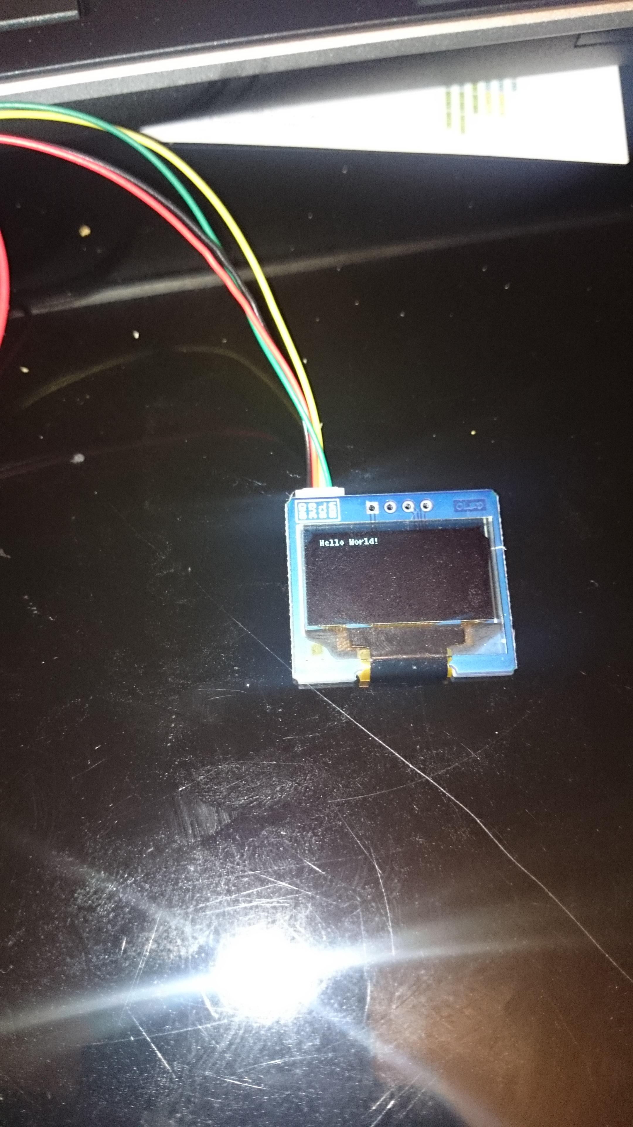
Posted at 2015-04-24 by @yerpj
Hi folks,
I spent hours trying to print something on some OLED displays I received from HobbyKing (http://www.hobbyking.com/hobbyking/store/__55110__Multiwii_OLED_Display_Module_I2C_128x64_Dot_MWC_AU_Warehouse_.html).
I guess the silicon is SSD1306.
However, Espruino tells me "Timeout on I2C Write Transmit Mode 2" everytime, in every configuration. I tried to downgrade Espruino, I tried putting some Pull-up on 3V3, I tried powering the module on 3V3 or on VBAT, I tried I2C1 and I2C2, I tried to decrease the clock down to 1kHz,I tried to modify the SSD1306 module in order to change its I2C address (browsed whole range from 0x00 to 0x7F), I tried to shake my display, I tried almost everything.... "I2C timeout" tells my Pico......
If someone used to play with those Multiwii OLED displays, I will be grateful to learn from your experience.
My current config is:
"I2C timeout" . . . aaaAARARRGHHHHHH !!!!!
Beta Was this translation helpful? Give feedback.
All reactions