Is there a limitation on "setWatch"? #6176
Replies: 1 comment
-
|
Posted at 2019-08-09 by Robin Fri 2019.08.09 Hello Peter. I see you are a recent forum poster. Welcome to the world of Espruino! There are too many questions here to answer accurately, such as which board, which version of Espruino, what is function visitorScoreUp() doing, how are the setWatch() functions initialized, etc. Many of us would like to assist with our time gratis, but please follow the forum post instructions at: so that we may be able to assist you here. Although I don't see a documentation comment that would limit the number, it most likely is in the way the setWatch() functions are being set up. Posted at 2019-08-09 by PeterD Ok sorry ;) I have a "Original Espruino", it is running version "2v04" "AT command Networking Only" and this is the function: function visitorScoreUp() { Every button is calling more or less the same function. Regards Posted at 2019-08-09 by @allObjects I see no reason why it should not work... Question is: how do you distinguish which button was pressed... or do you not need to know? ...looks like you do not need to know. How do you set your pins before you set the watch..."input_pullup"? Posted at 2019-08-09 by PeterD The project is a scoreboard. By pressing buttons (8 in total), the score and other things must be counting up or down. Everything is working, except the I have 8 setWatches activated. Then it is unstable the first minute after starting up. and only the first 4 or 5 setWatches are working. Posted at 2019-08-09 by maze1980 Gordon says 16 in http://forum.espruino.com/conversations/319081/#comment14191905 post #6. Maybe too much memory used, maybe an issue with analog A8/A9/A10 pins. Posted at 2019-08-09 by PeterD Ok, I've changed the wiring on the pins to C4, C5, ... C11. Posted at 2019-08-09 by Robin Fri 2019.08.09 Thank you for the detail Peter. That gets us all on the same page.
Have you tried to see if there are in fact memory leaks? Before first execution and just after upload, what is the result of Could you please check what the pinMode() is being assigned on each button tied to a pin. Please post the snippet on how the setWatch() functions are set up and how are they first fired. Is this being done on the Right-Hand editor side of the WebIDE or the console Left-Hand side?
Have your tried eight individual button setWatch() functions, or is that the 'unstable' you are referring to in #5? > Fr #6 'maybe an issue with analog A8/A9/A10 pins.' Is the pinMode() being set to 'analog'? You may be on to something here as setWatch() uses debounce for detection. The PWM (if being used that way) input may not have a detectable edge, similarly to a digital input. It is possible that analog input may work. I am not able to provide a definitive answer.
Try a value around 25-50. I'm not sure if that is a duration in msec or the number of detectable edges. It is likely that if 1000 is in msec, that is a full second and maybe out of the bounds of what you are attempting to track. If it is actual edge transitions, 1000 total may never be seen. See setWatch() link above. Posted at 2019-08-09 by PeterD Hi, I've run getPinMode() for each pin, and the return was "input" for all off them. There's no external resistor attached to the buttons. Is this needed?
The setWatch is on the right-hand side of WebIDE, as part of my program. If I run the program, at the start I see that the value's are rising on the screen, witch means that the inputs are "active".. ? and the functions are called. I've tried 25-50 as debounce, but then the values are rising faster. Therefore 1000. Posted at 2019-08-09 by PeterD Update: for each input I've used, and changed the debounce to 200. Now it looks stable !!! :) Posted at 2019-08-09 by Robin Fri 2019.08.09
Thank you for posting the memory check. Nothing out of the ordinary there for the Original Espruino board. What were the results of continued observation? I'm guessing no leaks, as a solution was finally found.
With as many combinations of pinMode() that are available, it is always a good idea to check the chip datasheet, link found beneath 'Information' heading towards the end of each specific Espruino board info page. A little study here goes a long way to understanding. p.86 It can be see the internal resistance is 30-50K with 40K being nominal. So depending on the design, in this case it sounds like the pin was just connected to the V+ side of the button, thus when specifying 'pulldown' the input signal to the pin would now be stable.
Depends on your design requirements. In general however, without the appropriate pinMode() a 40K resistance allows for a very small current, but must be overcome in order to change the detectable state. Having a direct short is not advisable, although will provide what appears to be the results one is after. It is always a good idea to use a current limiter when yanking a pin to any state, so the processor is protected. This also prevents shorting your supply and activating your home ceiling smoke detector! Use Ohm's Law here to calculate the appropriate size based on the voltage detected. Somewhere from ~1K -> ~4.7K -> ~10K would be in the right range, and low enough a value to provide enough current to override the internal ~40K nominal value. Posted at 2019-08-09 by PeterD Tx for your help!!! The next step will be building the big scoreboard. I don't know how complicated this is.. and what are the possibilities of wireless connection between 2 Espruino's. And what the possible distance of wireless communication is. Posted at 2019-08-10 by Robin Fri 2019.08.09
Rx Glad to help! Was in your shoes two years ago, writing my first line of microcontroller code and relate to some of the frustrations you may have had.
How so? Started with a project concept. Accumulated parts for the project. Wired both input and output. Then coded snippets to allow that hardware to work. Dug into the nuts and bolts of specific Espruino commands. Created forum questions in order to seek a solution. Waded through the responses and 'applied' that knowledge to each task. Combined the tasks into what even you describe as a 'successful' result, . . . and all in one day! I'd be pretty proud of your accomplishments!! What kind of range is needed for the wireless part? Could build a phone app controller with WiFi or BLE, could use two WiFi devices, RF using the SX1276 Some sample code using one device as a server station and as an access point The search box in the upper right hand corner of the main site is quite handy here: or even Google with the site: specifier keyword such as
Posted at 2019-08-10 by AkosLukacs That is a limitation of the microcontroller:
From the Known problems section in the Original Espruino Board's docs. Posted at 2019-08-10 by maze1980 So, I suspect the original problem was that the input signal was floating.
Posted at 2019-08-10 by @allObjects @peterd, the initial setup had two issues as pointed out by last two posts:
Latter a lot to take in when 'playing' with micro controllers - software and hardware - especially when new to the field. But there is no reason to be discouraged... it is exciting to enter this world and make it work for you. TL;DR: Current to flow is done by connecting something either to ground / GND / 0 Volts (V) or VBB / VDD / 3.3 / 5 V (https://en.wikipedia.org/wiki/IC_power-supply_pin), when the' other side is connected to the opposite' - 3.3V or GND, respectively - or simply: the negative and positive pole of a battery. When not connected, no charging or discharging happens. The electronic component inside the processor that is connected to a pin is a transistor - a component that can transmit or resist transmission of electrons (hence its name). A transistor has three (3) zones / connections, where one of them controls whether current - electrons - can flow or not - is/are transmitted or not - between the other two. For one of the two types of (Field Effect Transistors / FET) transistors, current flows when the controlling zone is charged, and no current flows when it is discharged. The controlling zone is connected to the micro controller's pin, and the other two zones to the detection circuitry. The fun comes when the pin is connected to both sides, but with the twist the one connection is permanent and thru a resistor which 'slows down' the charging and discharging' process, and the other one is only temporary connected - when the switch is pressed. Think of the controlling zone of a transistor as of a water bucket where a fat pipe - posing practically no resistances to the water flow - and another very slim pipe - posing a high resistance to water flow - is connected to, and think of the charging and discharging as of filling and emptying of the bucket. If the the fat pipe is connected to a (sufficient) water source and the slim pipe to the drain, the bucket will fill, because the draining isn't fast enough to keep the bucket 'empty'. A while after disconnecting the fat pip from the water source, the bucket will eventually be empty. Now think of a passage where passing is controlled by the 'fullness' of the bucket: when the bucket is more than two thirds full, things will begin to pass and the surge of passing can be detected and interpreted as the fat pipe has been connected: your switch has been pressed. Otherwise, when bucket is less than a third full, nothing passes / passing stops (decrease of passing can be detected to... and the difference is in the option: trigger / detection "raising" vs. "falling" vs. "both" - and the debounce helps to ignore erroneous "sporadic gulps" or "sporadic throw-ups"... you want to detect only real steady and solid ones... As for thinking: with now permanent drain of the bucket, the bucket would eventually be empty after a very long time: all water evaporated... (if conditions right). This explains why the first few button presses worked... but after the gates were charged / discharged, nothing more happened... I guess you can make the bridge back to the Enjoy the journey in your new world... youtube has tons of good material helping you along this journey... (of course bad and boring - copycats - too... to understand BJTs and FETs -two very different transistor types with two main types of each you can find at: https://www.youtube.com/watch?v=7ukDKVHnac4 and N MOSFET Experiment ...and finally https://www.youtube.com/watch?v=p34w6ISouZY. The third one will confuse you first even more, because when current was discovered and defined, the atomic structure of materia and electrons were not yet... and current is reverse to actual flow of electrons... haha... ...and putting the icing on the cake - as it just did for me.. Unintended - this youtube caught my attention... https://www.youtube.com/watch?v=1uEmX5XClPY ... LOL ... and even more LOOOL watching the youtube companion's clip. Posted at 2019-08-10 by @allObjects To get your final board going, connect an ESP-8266 ESP-01 to your original board and get yourself an Espruino wifi. One you operate as an access point with Web server and the other with an plain station and 'browser' that refreshes periodically with an http request to the server and displays the result on your display the way you already do... (another option is to go for bluetooth, but I would start with Wifi / Wireless LAN). Posted at 2019-08-11 by PeterD Hi @ all, Tx all for your help and support. My first objective was to build a "controller". This controller will be connected to a large screen. Wired or wireless, that is not yet decided. https://www.youtube.com/watch?v=5h7a_aExTEw Posted at 2019-08-11 by @allObjects Looks amazing... the arrangement of the buttons has just to be declared as "ergonomic" - no doubts remain. For the big board, did you consider to use a RGB LEDs / Neopixels for the board? see: Large Display for Game Board. --- You would have to used strings higher pixel density (this is 30 /m, but there exist 60 /m and even 144 /m). And as you can see in the code, they are driven by the Espriuno Graphics object... which you already know how to code - write strings, draw lines and shapes, etc. Posted at 2019-08-12 by pankleks In the topic of setWatch limitation - I have a strange behaviour of setWatch. Code should count impulses per second, and it does. However strange thing is that at low speed it counts 45-50 impulses, at high speed (~x2) it counts 43-48 impulses. Clearly expectation was quite the opposite:) Assuming code and wiring is ok - I was wondering if maybe I'm hitting speed limitation of Espruino - which is simply not able to process frequently enough impulses. I'm using ESP32 and Espruino 2.04 Posted at 2019-08-12 by AkosLukacs The problem might be the speed. Have you tried the Encoder module? Posted at 2019-08-12 by PeterD For the big board, I'll use the WS2811 leds (Neopixel) Posted at 2019-08-12 by pankleks @AkosLukacs no, but if I check source code of this module I'm doing pretty much same thing. Posted at 2019-08-12 by AkosLukacs The encoder module might be slightly better, because that is minified (less characters == faster execution). Posted at 2019-08-12 by AkosLukacs Nice! I think if you use black background, that increases the contrast in bright daylight. Posted at 2019-08-12 by pankleks @AkosLukacs thanks - I will make some tests in coming days and share results. I was just wondering if there is a better way of doing this. Posted at 2019-08-12 by Robin Mon 2019.08.12 Hi @pankleks, I recently thought (wrongly) that setWatch() was problematic. Gordon demonstrated a solution with the following snippet: It is likely that the Javascript needed to process the digitalRead() is the issue. My really rough timing observation is that Espruino needs around 50usec overhead to make the call, and another variable amount to get the rest of the instructions processed. I'm clocking data accurately with 2usec pulse width, 500KHz spaced at tenth second intervals. Are there any setIntervals() running? What does the datasheet show for max readings? Are we Absolutely certain that the interface electronics is as needed and that 'pull down' is the appropriate mode? Both devices share a common ground? Posted at 2019-08-12 by Robin Mon 2019.08.12 Hey @peterd, you never cease to surprise us! Another two days and a rough finished proof of concept done towards your project goal. Curious, did you retain a continuous strip of the WS2811 or are they individual bulbs? Wondered if you are using small 8 element arrays for the individual seqments, and just chaining them together in memory to form the digit? Would you mind sharing some code tid-bits? Any chance for an image of the back side to show Neopixels and board interface wiring? The video demos your ideas. It will be cool to see in use!! Your fans will luv ya! Posted at 2019-08-12 by maze1980
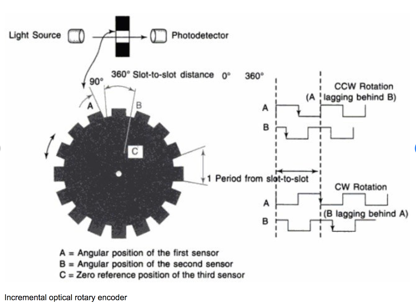
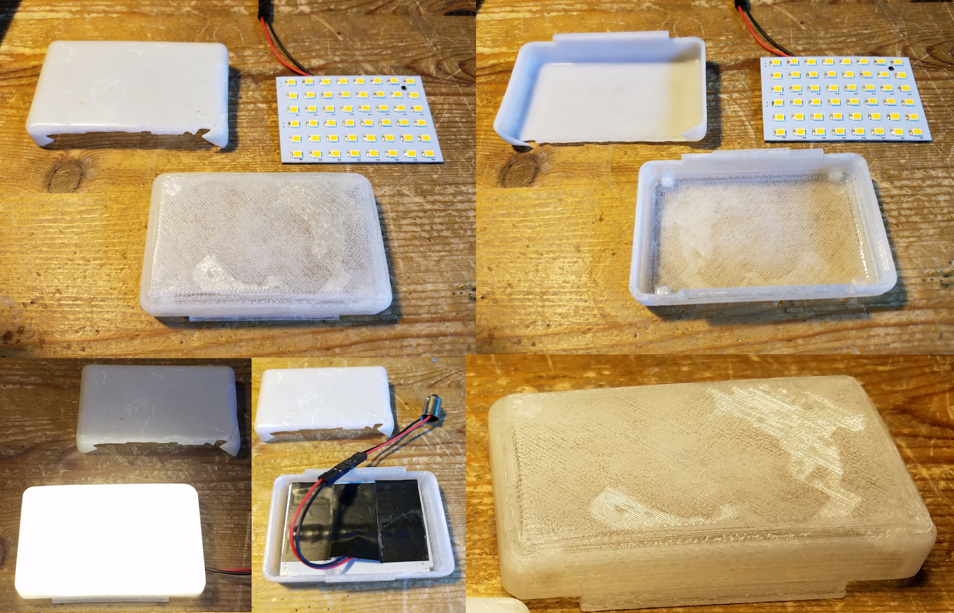
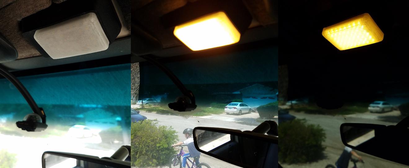
Visible is easy, readable is harder. Shading helps, as known for traffic lights. And more LEDs help, I'd go with 144 LEDs per meter strips, not with individual LEDs. And you'll need cooling, a custom PCB with a hole below each LED and a powerful fan in the back sucking in air from the front would help - or just don't go to 100% brightness (R+G+B) for too long. Posted at 2019-08-12 by @allObjects @pankleks, you may face the issue that by the time you read the pin, it is a bounce... because you do not debounce. But even a solid debounce may not help you because you may run into the speed / frequency issue. There was another conversation about the encoder run with If you do not use a mechanical contact / switch based decoder but rather an optical (bare bone) one, following comments apply only partially. If it is electronically - with lights - some kind of Schmitt trigger with appropriate hysteresis has to be applied. The frequency issue - overrun - you can detect by looking at the error flags with Handling mechanical switches IS a challenge, because of the bounce and its even more so because of its unpredictability (heavily dependent on materials / quality / cleanliness / etc. of the switch) . For "slowly" changes in states you may get away with a simple approach. But to reliably detect you have to catch not only the good states, but also reject the bad states. I still believe that JS and in particular Espruino is fast enough to handle that. - *** Try your code with an original Espruino board... *** (or at least with an ESP-8266 where there is no - or much less of - layering of SW is involved between the actual pin and your watch callback function, HW event handling and reading the pin state. ESP-32 - though considered powerful in regard of computing power - is not that suitable for handling HW events and interfacing HW and JavaScript as @gfwilliams's implementation on STM32 and MDBT42). What I would do - and did in some of my applications where buttons are involved - was to create a state machine which is aware of all the good and bad states and all possible timings and let the To reliably detect a motion on a rotary/linear decoder you need two events from different sensors / pins to confirm an actual movement. You cannot derive from an on or off of a single sensor / pin wether it is a clockwise / counter-clockwise / forward / backward movement: it could just be a jitter. With mechanical sensors (switches) you have to have the guarantee that when the second one shows on event, the first one has to have stabilized / debounced. Only then you can be sure about the state of the first one. In basic hardware implementation you use a pairs of interlocking negative and positive pulse triggered RS-flip-flops. Luckily, this you can emulate / simulate w/ software... and that is what I meant with building a state machine. (Btw, fat-arrow functions have limitations - see https://developer.mozilla.org/en-US/docs/Web/JavaScript/Reference/Functions/Arrow_functions - but as I see nothing in your code that would hint that these contribute to the flaky results you experience.) ...for some info about encoders see https://www.researchgate.net/publication/305649159_Re-gripping_analysis_based_on_implementation_of_slip-detection_device_for_robotic_hand_model - from where the attached pic is from - and https://www.analogictips.com/rotary-encoders-part-1-optical-encoders/ (interestingly - only optical and magnetic encoders are mentioned...) Attachments: Posted at 2019-08-12 by @allObjects @peterd, I was going for a full dot-matix display... but your 7 segment does the job as well... with much less effort... You can browse several of my conversations that deal w/ 7 segment displays and how to logically control / drive them, for example Retro Bubble Displays driven with 74HC595. Since you plan to use Neopixels, instead of the multiplexer reading out the character / digit buffer and mapping it to the 7 segments, you write a Neopixel data stream composer that is reading out the buffer. Furthermore, you do not need to interval the update of the display since you have knowledge of the update events from your controller. You still can use an interval based approach, but the the first thing it does is check for change since last time.... and because you use only a few bytes for representing the scores, memory is not an issue... For the 7 segments think of some 3D printed segments from partially transparent filaments, ten you need not that many LEDs and have less heat dissipation challenges... (but still be conscious to protect critical elements from direct sun exposure). Posted at 2019-08-12 by @MaBecker Just found this cool 7 segment design https://blog.hackster.io/ginormous-7-segment-display-with-neopixels-f96fcd168704 Posted at 2019-08-12 by @allObjects @MaBecker, thanks for posting this link. I would construct it with a bit more diffusion effect. I recently made some practical - micro controller free - 3D print and LED application, pub'd 'somewhere else':
I see the value of using Neopixel because then no multiplexing is needed,... offloads the micro controller and allows even colors. Attachments: Posted at 2019-08-12 by PeterD For the big scoreboard, I think I'm going to use a thick (40mm or more) black MDF wooden board. Posted at 2019-08-13 by @allObjects ...will be quite a heavy board... what do plan for overall size? ...power supply? Posted at 2019-08-13 by maze1980 Diffusion kills brightness. From some distance it's impossible to identify individual LEDs on a 144 LEDs/meter LED strip, saving the diffusor. You've already posted a video - did you try this outside at daylight already? Posted at 2019-08-13 by PeterD The board will be 1.8 by 1 meter (approximately). Version 2 will be based on 64x64 led panels. But I don't have experience whit this. It should be nice if I can control this by HDMI. But maybe I need a kind of converter to control 50 of these panels by HDMI. For the moment I plan to complete the "low cost" model first ;) Posted at 2019-08-14 by @allObjects Lexan is stronger - practically unbreakable - and allows you to go lighter. 40A is plenty... full bright - white - pixel takes 0.06A, which means that you could run more than double the planned 300 ones. To simplify your setup, you could have the segments 3 dimensions, like letters that are put up on a storefront. To go completely contrast safe, think of something like flip-dot - with or without additional LED or split flap design... ...or this I came across a while ago: (electro) mechanical 7 segment display - https://hackaday.io/project/161215-largemechanical-hand-activated-7-segment-display and https://hackaday.com/2019/01/26/7-segment-display-is-3d-printed-and-hand-cranked/ ... commercially available... just not in the size you are looking for... https://www.youtube.com/watch?v=hJ4INheOEjE - with some modifications... you may already researched this anyway. Posted at 2019-08-14 by PeterD what do you mean by "flip-dot - with or without additional LED or flip-card design..." ? Posted at 2019-08-15 by @allObjects Flip dot display: And there are flip dot displays available that have in addition to each flip dot also an LED that is on if the flip dot is 'on': https://hackaday.io/project/159415/logs?sort=oldest The split flap display is like this: https://www.youtube.com/watch?v=lW0fk_sIdic
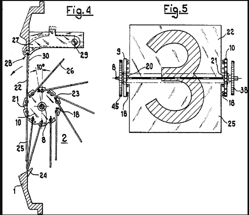
Instead of split flaps, you can also use rotating disks... probably the simplest to implement with a few steppers... Attached is split flap tech drawing / cross cut as found on wikipedia Attachments: |
Beta Was this translation helpful? Give feedback.
Uh oh!
There was an error while loading. Please reload this page.
-
Posted at 2019-08-09 by PeterD
Hi,
I'm workin on a project.
I need to scan 8 external buttons.
Therefore I use the setWatch function.
But it looks like the Espruino can't handle 8 setWatch functions.
If I disable (make a comment of it) a few setWatch, then it is working fine for these buttons.
The pins I used are C7, C8, C9, C10, C11, A8, A9 ad A10
Tis is the setWatch line
setWatch(visitorScoreUp, A9, {repeat: true, edge: 'falling', debounce: 300});
The other pin of the button is connected to the GND
Regards
Peter
Beta Was this translation helpful? Give feedback.
All reactions