WiFi + Bluetooth #6362
Replies: 1 comment
-
|
Posted at 2020-11-10 by @gfwilliams Your best bet is to use one of the Bluetooth devices and to add WiFi to it - generally you'd use an ESP8266 module which handles all the TCP/IP and communicates via Serial.
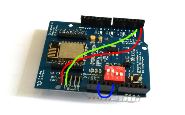
Hope that helps! Posted at 2020-11-10 by user118421 Many thanks, I'll test both :) The wifi modules are not available in your store? Do you know if the below would be compatible with Pixl.js and MDBT42Q? Or is there any other model you recommend? Posted at 2020-11-10 by @gfwilliams Great! No, unfortunately I don't stock them at the moment... The Crazepony ones look spot on, and the arduino shield might work, but I'd recommend https://www.amazon.co.uk/ARCELI-ESP-12E-ESP8266-Wireless-Arduino/dp/B07DMZVQ4D/ref=sr_1_14 as that one looks identical to the one I've tested Posted at 2020-11-10 by user118421 Brilliant - thank you very much - both ordered and looking forward to test :) Posted at 2020-11-11 by user91203 If there was a device that had both, you could run EspruinoHub on it... ☺ Posted at 2020-11-13 by user118421 I now have the WiFi shield but fail to understand the instructions here . I'm sure it's just me lacking knowledge but I don't understand the difference of using it 'as-is' or 'as a shield'. Do I need to re-wire or solder anything or can I just connect the pins from the shield to the Pixl.js? There seems to be different ways of connecting described on the page and I'm not sure which parts of the instruction I need to follow to add the wifi shield as simple as possible. Grateful for any clarification that could help me :) Posted at 2020-11-13 by @gfwilliams I'd suggest the 'as-is' method. Basically, plug the shield onto the Pixl.js, but then you need to add an additional 3 wires, which you can do on the shield itself:
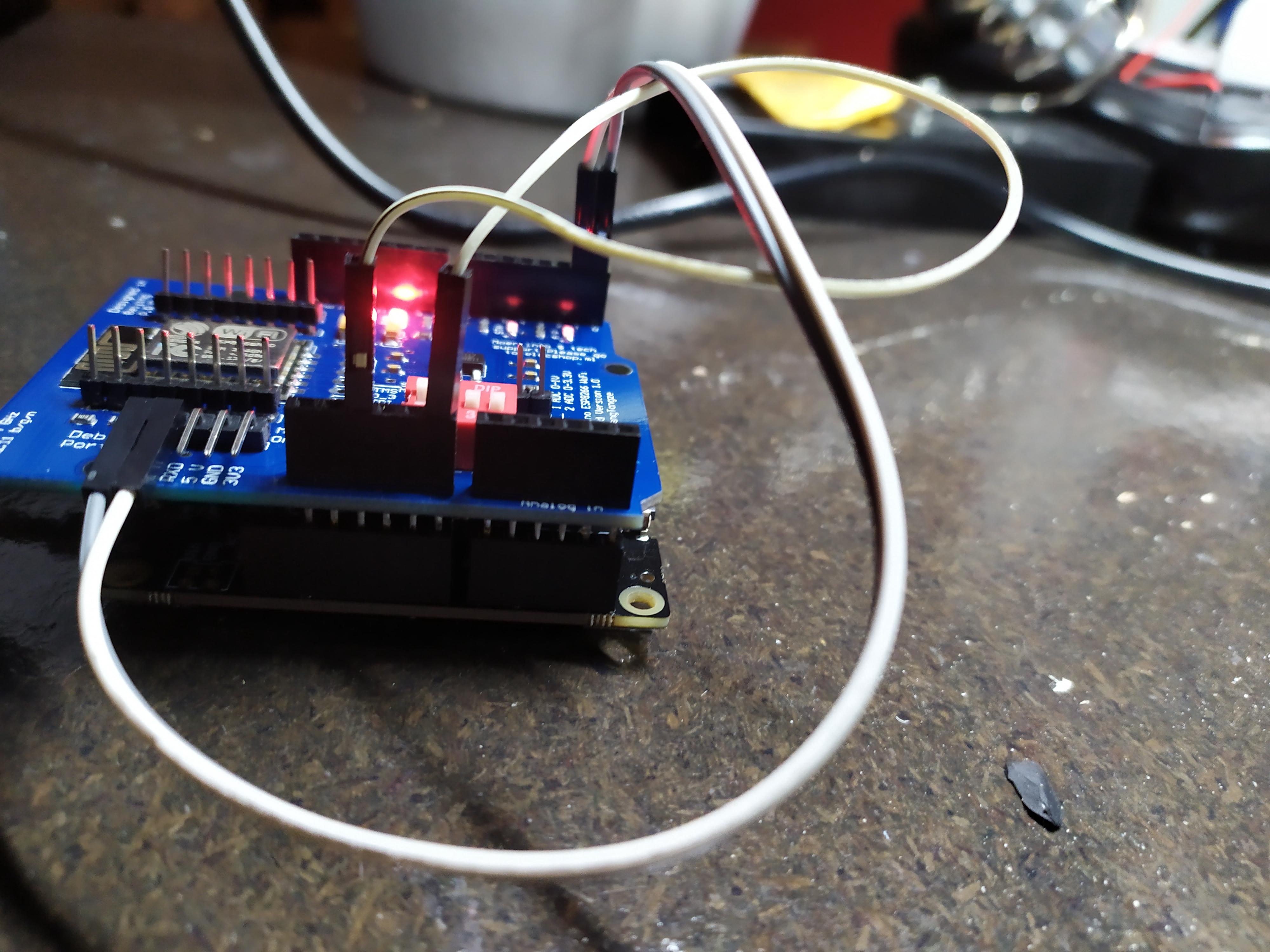
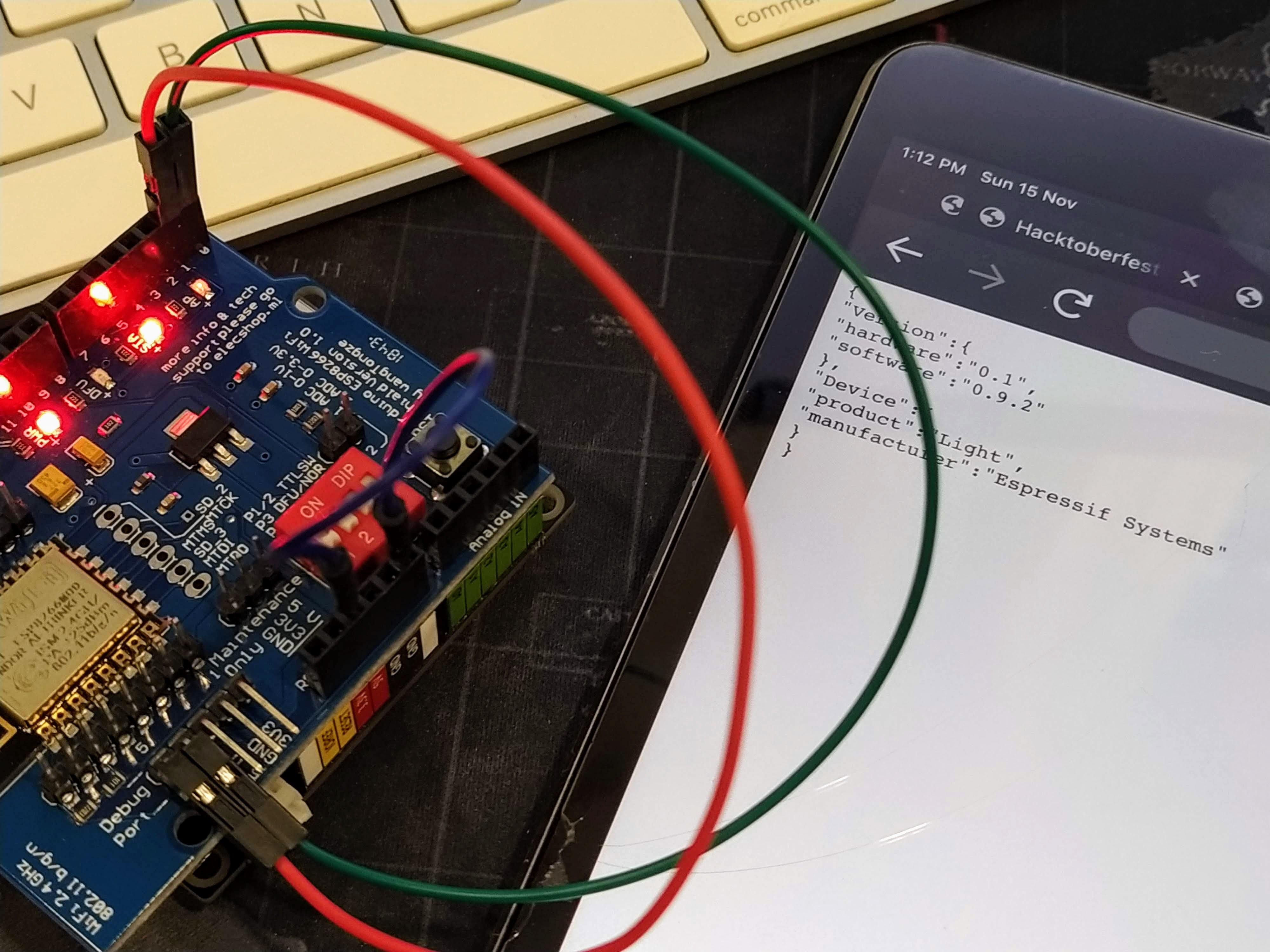
The third one is something you can do with a solder-jumper on Pixl.js itself, but in the interests of not getting a soldering iron out you can do it just with wire. Attachments: Posted at 2020-11-13 by user118421 Many thanks for the super clear reply and image! I followed it but unfortunately I receive the error; when running the below code (from the instruction page). Any idea what I may be doing wrong? Attachments: Posted at 2020-11-14 by parasquid Espruino Wifi requires the AT commandset firmware be available on the wifi shield. See also https://www.espruino.com/ESP8266#gotchas Maybe you need to check if you have the correct firmware on the shield? https://www.espruino.com/ESP8266#firmware-versions Posted at 2020-11-14 by user118421 I get an error when trying to verify the firmware version. Running this; Gives me this response; Posted at 2020-11-14 by parasquid I don't know if your Espruino has Serial2 but have you tried Serial1 like you did in your previous example? Posted at 2020-11-14 by user118421 Changing to Serial1 returns empty strings; Posted at 2020-11-15 by parasquid I brought out one of mine that I bought sometime back and didn't actually use, and it looks like these boards have some sort of demo firmware in them by default (not the AT command set that Espruino or Arduino is expecting). You can check if yours is the same by turning it on and seeing if you have something like "ai-thinker" show up in your wifi networks. If I connect to mine with the password "ai-thinker" and go to I see some information as a webpage, which tells me mine does NOT have the AT commandset. You might need to flash your own firmware on the shield in that case as mentioned here https://www.espruino.com/ESP8266#updating-esp8266-firmware Maybe others might have more ideas that don't involve flashing the wifi devboard? It's relatively easy for me so I don't really think twice about it, but others might have a different technique. Attachments: Posted at 2020-11-15 by user118421 @parasquid - many thanks for helping and making the effort to test! I see the shield as FaryLink_ABC123 in the network but I'm not able to get the info page you mention. Anyway some googling indicated that these shields probably needs new firmware so I'll follow the instructions you linked to. I had to order the USB-TTL adaptor described so have to wait for that though. Posted at 2020-11-15 by @allObjects @user118421, you not need the USB-TTL adaptor, you can use the Espruino as that link. You can configure it to pass data thru... that is how I updated my very first ESP8266 ESP-01 and later the ESP-09. Before you though move into more things, check the wiring, measure voltages, and - flip tx w/ rx. Even though latter is trivial, I was not the first to have it the other way around... : Check this conversation about Espruino on ESP8266 ESP-09 - 1 powerful cm2 out. Even though you see the USB-to-TTL adapter on the first pic, reading thru the posts shows you that I did talk to the module thru an Espruino first, and even updated the software. I assume you use a Pixl. Did you power it with 5V from USB? Can you measure the voltage on the ESP8266 Module? It may well be that there is something missing. There two links you may check out as well (if you not already did): https://claus.bloggt.es/2017/02/26/arduino-esp8266-wifi-shield-elecshop-ml-by-wangtongze-comparison/ and https://claus.bloggt.es/2017/01/14/using-esp8266-shield-esp-12e-elecshop-ml-by-wangtongze-with-an-arduino-uno/ To just talk to the ESP8266 - shield not stacked onto the Pixl - connect D0, D1 and GND from Pixl with RX, TX and GND of the shield, and 5V AND GND of a 5V source to GND and 5V of the shield, all debug port pins. Furthermore, check in what mode the module is. The way I interpret the red-white dip switches on the shield, they should be in the run mode... but you never trust... you measure. Even though I used the ESP-09 to describe required signals on the pins (ports) for run mode, the pins (ports) are the same on ESP-12. ESP-12 just exposes more pins (ports) than the ESP-01 or ESP-09. For updating the ESP8266 software thru Espruino, I took the hints from https://www.espruino.com/WiFi - Regarding the code you posted in #9, I would place the invocation of your Posted at 2020-11-16 by @gfwilliams
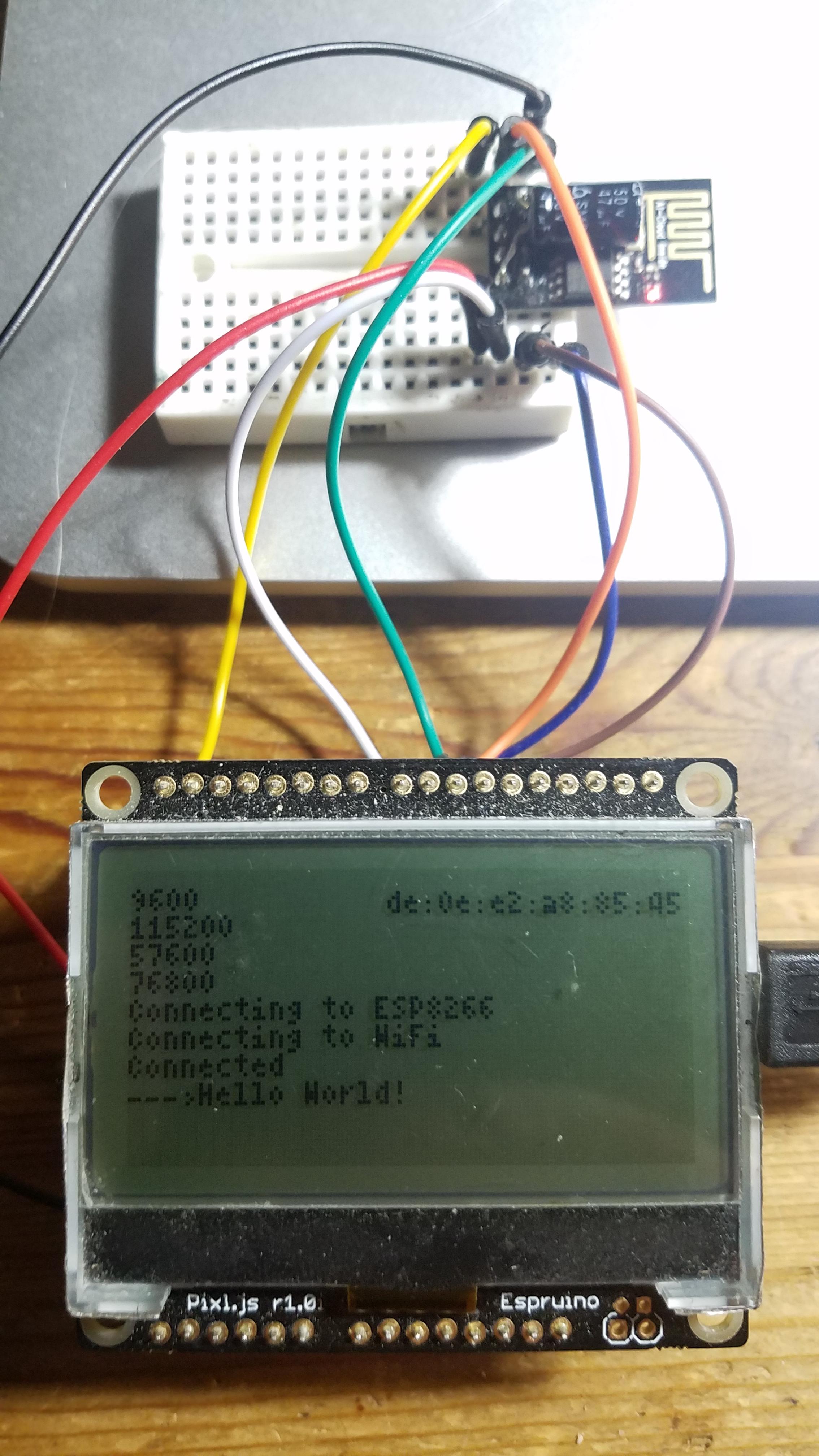
Argh - so I guess that means it has been programmed with some other firmware. However, it looks like you might not have set SW1 and SW2 to 'off'? https://www.espruino.com/arduino-esp8266#using-as-is So maybe you could do that and give it another try with the test code you'd posted above in #13 ? I actually recently added something to handle firmware updates to the Espruino WiFi via the Web IDE, so if you don't have a USB-TTL converter then let me know and I can see if I can bodge something up to allow you to do firmware updates straight through Pixl.js. Posted at 2020-11-16 by @allObjects Dug up the ESP8266 (black PCB) and connected it to a Pixl.js This is the code I used to detect the baud rate, and this then get the hello page. After upload of the code, I enter in the IDE console: And get this back: Because 'clear' shows with 115200 baud, I enter Unfortunately, I have no plain ESP-12X for testing, but I have another ESP-01 (blue PCB) with even older firmware. I'll try to update it. And it never got beyond (PS: Screen shot of PixleJS w/ Attachments: Posted at 2020-11-16 by user118421 Many thanks for all advice! Yes, the Pixl is powered with 5v USB. If I measure on the ESP8266 it shows 3.3V. Flipping tx with rx gives same result (empty string) I also still just get empty strings as response if I set SW1 and SW2 to 'off'. Same thing with the first piece of code in #18 from allObjects which returns this; I did order the USB-TTL converter so I'll give the firmware update instructions a shot when I receive it. I'll update here when I have tried that. Sorry if I missed trying something out but as I'm all new to this it's easy to get lost in all details :) Posted at 2020-11-16 by @allObjects @user118421, your device should at least 'cough'... I notice that on subsequent try, all can return with space... But when I disconnect all from power and reconnect power, then upload the code again, and make a run, I get responses ('coughs' and clear). Posted at 2020-11-16 by @allObjects @gfwilliams / @user118421, I tried with this piece of code modelled after code I used previously and is also mentioned at https://www.espruino.com/ESP8266 to update my 'blue' ESP8266 ESP-01: This is the console output, indicating that connection does not happen. I'm not sure about the port - I used /dev/cu.Blue... and /dev/tty.Blue... - but both fail the same way:
Posted at 2020-11-17 by @gfwilliams @user118421 thanks for giving this all a go - the USB-TTL converter will definitely be the easiest way to get this working. You mentioned you bought an ESP01 as well? You could try wiring that up to Pixl.js with some jumper cables, and that will likely work straight away. @allObjects Bluetooth LE UART doesn't appear as a device in MacOS/Linux, so unfortunately what you're proposing won't work :( You could go to https://espruino.github.io/EspruinoWebIDE/, open up https://github.com/espruino/EspruinoTools/blob/master/core/flasherESP8266.js#L107-L131 in the Chrome Devtools and change the pin names, then run the flasher... Also, Pixl.js doesn't have a voltage regulator that's specced to be powerful enough to handle powering an ESP866 directly (hence why I'd suggested the board). However it's unlikely to cause any problems - it might just not work reliably. Could you actually get a WiFi connection on it? That's great news if so - it makes life far easier. Posted at 2020-11-17 by @allObjects Ic. Assuming the regulator on PixlJS was chosen with the optimum for PixlJS needs in mind, and a cap big enough to help over the current bursts could cause a reset - or at least a brown out - on connection. So you suggest a change within the IDE. You already use that solution for flashing the ESP8266 on the Espruino-Wifi. You mention that an earlier post of this conversation. I looked at the code and it is really the most user friendly solution: just wiring the things 'correctly' and use the flasher dialog to execute. I took a peek at the code and wonder how to make the different pins known to the flasher. Currently, it is fixed to the pins as defined for Espruino-Wifi. But if I wire Original or Pico up the same way, I can use the current IDE to flash 'any' of the ESP8266... (except you check - for 'safety' and against 'brazen' users - the connected board... haha). Technically, a configuration option for the pins would do it - given for Espruino-Wifi - and user define-able for other boards. And for passing to the function, the option object could be the candidate. For the first, simple implementation with a lot of user responsibility, an extra entry field for passing a pins object in JSON would be just fine. Empty field means the Espruino-Wifi defaults, not-empty field uses JSON.parse() for formal correctness and simple check for presence of the required pins provide already enough user safety. Posted at 2020-11-17 by user118421 I have not received the TTL USB adaptor yes but tried this; I connected the Pixl.js to the ESP8266 Esp-01 like this; Then ran this; The result; However, when I then run this the Pixl.js just disconnects from my PC Espruino Web IDE bluetooth and enters into a boot loop..; Posted at 2020-11-18 by @gfwilliams
Ahh - that's probably because of the power usage issues mentioned above. That's a shame. Still, at least you know that when the correct firmware is on the ESP8266, it'll all work ok. I'll work on a tweak to the Web IDE firmware updater for you, which should allow you to update without the dongle. Posted at 2020-11-18 by @allObjects @user118421 you are up to something! - Besides the shield with an ESP8266 ESP-12X module, it looks like you connected a plain ESP8266 ESP-01 - same as in pic in post #18. In the past, when my ESP8266 ESP-01 was flailing, is was because power was not stable enough. When ESP8266 is enabled, a calibration happens that draws quite some power. If not enough is available, the ESP8266 browns out / reboots... to just end up at the same spot and reboot again,... over and over... The issue can be resolved by adding a decent capacitor. The capacitor has a capacity of 47uF and is directly soldered onto the module. A good connection on a breadboard is though sufficient as well, as you can see at ...1 powerful cm2 (where capacity was about 5x...: 220uF). As @gfwilliams though pointed out, I may just have had luck that my test with PixleJS 3.3V power worked, but may not be reliable. Posted at 2020-11-18 by @gfwilliams Ok - it's now live!
|
Beta Was this translation helpful? Give feedback.
Uh oh!
There was an error while loading. Please reload this page.
-
Posted at 2020-11-10 by user118421
Hi, I want an Espruino board with both WiFi and Bluetooth but it seems like none has both? What is the best solution to achieve this? Is some kind of combination possible and if so how are the devices connected?
Thank you
Beta Was this translation helpful? Give feedback.
All reactions