Counting Nerf Darts Inside the Clip (Hall Effect, Restive strip, Digital Calipars) #791
Replies: 18 comments
-
|
Posted at 2015-09-06 by @allObjects The IR proximity sensors have a very 'switchy' behavior: on or off... You may be more successful with a ultrasonic sensor. Size of the magazine and the fact that it is a 'closed environment' (with lots of wall reflections) may pose extra challenges. Other measurements could be implemented by placing a 'resistor-band' (heavy computer magnet tape) inside the magazin body and a wiper to the moving part. Placing the ends to 3.6 and 0 V and reading the wiper's voltage with an analog read will do a good job. A cross cut could look like this: You can use the spring as the 'wire' from the wiper to the wire you connect to the analog input to avoid having moving wires in the box interferring with the spring: solder the wiper to the moving end of the spring and the wire to the fixed one at the bottom of the clip. The regular tape works also as an insulator and distancer so that only the wiper touches the resistor tape and not the metallic - conducting - spring. You may anyway have a tight situation with the tapes taking up some space as well. |
Beta Was this translation helpful? Give feedback.
-
|
Posted at 2015-09-07 by @gfwilliams I'm afraid the TRCT5000 probably won't be great for that - as @allObjects says it's very much on/off. Another option I've come across recently is actually to use a magnetometer. If you put a neodynium magnet on the plunger that pushes the nerf darts up (I guess there is one?) and position the magnetometer correctly then you should be able to measure the direction of the magnet - and so work out where the plunger is. It'd need some experimentation, but the magnet itself should be so much stronger than the earth's magnetic field that the angle of the nerf gun won't really matter. |
Beta Was this translation helpful? Give feedback.
-
|
Posted at 2015-09-07 by MrTimcakes I think the Hall Effect sensor is probably the best suggestion so far as the IR solutions (even the Sharp GP2Y0A41SK0F) would probably get blocked or interfered with by the walls or the spring. However @allObjects 's resistive tape idea is also good. Thanks for your replies. P.S Nice to see your back Gordon, hope you had a nice time. |
Beta Was this translation helpful? Give feedback.
-
|
Posted at 2015-09-07 by MrTimcakes |
Beta Was this translation helpful? Give feedback.
-
|
Posted at 2015-09-07 by @allObjects @ducky, I'm not sure you want to go for a 'switchy' Hall Effect sensor... you will end up with practically the same behavior as with the IR proximity sensor. There are various Hall Effect sensors. Of course, the most used ones are the switching ones. They have usually Schmitt Trigger behavior / built in, and some they go even further and require a polarity change to switch to the other state. Therefore, you have to find a Hall Effect sensor that just measures the intensity of the magnetic field (see this intro]). You need something like Honewell SS49/SS19 Series with 5v, GND, and Hall Voltage out. Hall Voltage is related to the intensity of the magnetic field. |
Beta Was this translation helpful? Give feedback.
-
|
Posted at 2015-09-07 by MrTimcakes Ah, I was under the impression Switchy Hall Effect sensors were Magnetic read switches, my bad xD, Would the HMC5883 work for this application though? |
Beta Was this translation helpful? Give feedback.
-
|
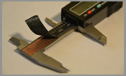
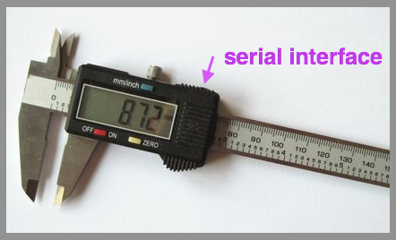
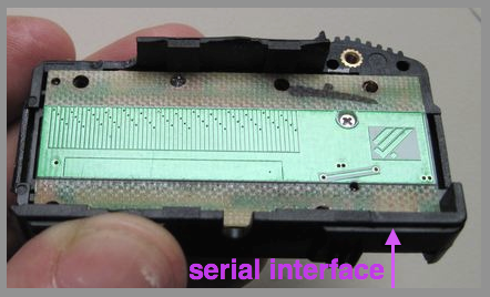
Posted at 2015-09-07 by @allObjects HMC5883 provides you with the angles relative to the magnetic field vector... For example, a regular compas shows you the deviation from north, so does of the sensor when z perpendicular to the magnetic field vector. When you tilt, you get different values for xy and non-zero for z. As you will become aware when reading the Erdmagnetfeld wiki entry, the calculations it becomes quite complex depending where you measure because the field is heavily 'bent'. The compas sensor tells you only which direction to the magnetic field vector you are heading. I do not know how they exactly work, but they could include 3 orthogonally oriented hall sensors... (Magnetometer and Erdmagnetfeld). You may give it a try, but I doubt that it works well enough, because I'm not sure if a neodine can create a far enough reaching field of strength that the earth's field does not really matter. How much (inch / mm) does the plunger in the clip travel? This site may be of some help. I still believe that a resistive technique is the most affordable and still accurate enough approach. If you want to get down to a 1/100 inch/ 3/100 mm, you can 'hack' a cheap ($10..$20 for 4..6 inch 10..15 cm) digital caliper made of metal or composite material... and most of them have even some kind of serial interface. If you can 'hack' the built-in chip ('s scaling factor - may be through the serial interface), you can even modify the displayed value to match the number of rounds left!... ;) - let me know how far you get with that... we could ask the manufacturer to add a third setting: inch/mm/rounds :||Attachments: |
Beta Was this translation helpful? Give feedback.
-
|
Posted at 2015-09-07 by MrTimcakes Where could I source some resistive strip? Ebay? Or perhaps some paper with HB pencil Led could work. I also thought of the caliper but it is too expensive to apply to multiple clips at £10 a clip. Even if all these ideas fail I guess I could resort to assuming the clip is full and counting down after one is fired, although id like absolute measurement. |
Beta Was this translation helpful? Give feedback.
-
|
Posted at 2015-09-07 by cwilt What about measuring the electrical resistance of the spring? It may require some amplification. Assuming it is metal. |
Beta Was this translation helpful? Give feedback.
-
|
Posted at 2015-09-08 by @allObjects @cwilt: With a general 10-7 OhmMeter resistance of steel, it is quite a challenge to confidently detect a delta of almost nothing... copensating for environmental effects may even be a bigger hurdle (as it is also for a magnetic solution). The initial value and variation of magnetic field of a neodyn is 7+ orders easier... Btw, resistance vs tension was tried but failed, succeded capacitive (with telescopic coil spring). Capacitve could a solution (see bottom of the post). Back to @gordon's suggested magnet field solution: Assuming, @ducky's average magentic field from the earth is about 0.000'048T or 0.48Gauss (see text and chart and calculated); electromagnetic field intensity measurement unit conversions: 1 T(esla) = 10'000 G(auss). Assuming the plunger moves 4 inches, the magnetic field of an axially (+-y) magnetized neodyn 42 disk of 1/4" (0.25) thickness and 1/2" (0.5) " diameter varies with a 4" plunger movement: with y=0 for: with x=0 for (calculated, calculator courtesy of K&J Magnetic Inc. based on their product). Arrangments starting farther away from the magnet are easier to measure (may be...see next paragraph)... Courtesy Honeywell Solid State Sensors SS49/SS19 Series Analog Position Sensors: Hall Effect sensor's data sheet(s) and magnetoresistive-hall-effect-applications applications notes should be able tell. Wether the placement with magnet in the plunger and sensor at the bottom of the clip or vice-versa has to be figured out experimentally, as well as what the effect of the most-likely steel spring has. With the earth magnetism taken into account, things look pretty bleak for distances of 4": Conclusion: Measuring over a distance of 4" is a challenge... a complicated calculation with a x,y,z device to compensate for the (locally known) x,y,z components of the earth magnetism may work, though. Alternatives:
A optical - reflecting - solution: A mechanical-optical solution: A laser solution: A mechanical-resistive solution: The capacitive solution:
Btw, how many rounds are in a clip, and how much moves the plunger? kind-a got it a bit better: @ducky, is that what you are talking about? @ducky, thanks for challenge! |
Beta Was this translation helpful? Give feedback.
-
|
Posted at 2015-09-08 by @allObjects Having seen the modifications, this is a possible solution:
The drawback of this solution are the moving wires... 3 of them... so I'm thinking... |
Beta Was this translation helpful? Give feedback.
-
|
Posted at 2015-09-08 by @allObjects An electro-mechanical solution:
When the collar is moving up and down the guide, the spring's contact portion falls into the valleys of the guiding tube and contacts the inner tube/rod creating pulses ou watch. Again, use options {edge:"both", repeat:true, debounce:aLot } to handle the behavior. Notes:
Whit this solution, you still have no absolute measurment. A manual preset is required (or loading while connected). The enhancement: use just pieces of tube/rod for the inner rod at the contact/valley locations and solder resistors between them. This will give you the abslute measurement. You use a setWatch for the event that triggers a fast seqence of analogue reads to handle the 'noise'. You can get rid of the count, or keep it and use it as a cross-check if count has been preset manually. For sequncing and powering and measuring, check out Resistive Touchscreen directly (no touch controller). Sequence looks like:
Note: setWatch and analog read use the same pin... internal pullup can stay on, because you have to calibrate anyway (of course, precision resistors <=1% are 'useful', since you want to use multiple clips with the same calibration). Btw, I still belive that there is a simple ultra-sonic or simple IR solution: simple because it would most-likely not need a modification of the clip and could be installed in the gun. Take a look at this overview, where minimum distance is very small and maximum distance includes the plunger moving distance, and resolution is less than (half) the diameter of a round... STMicroelectronics VL6180X Proximity and ambient light sensing (ALS) module and AN4545 Application note VL6180X, Sharp GP2Y0A41SK0F GP2Y0A51SK0F Analog IR Distance Sensor, Vishay VCNL4000 Fully Integrated Proximity and Ambient Light Sensor with Infrared Emitter and I2C Interface, BaxBotix Ultrasonic Sensors. |
Beta Was this translation helpful? Give feedback.
-
|
Posted at 2015-09-08 by @gfwilliams Well, I'd have said the HMC5883 should work fine. It'd be worth some experimenting. The digital caliper is an interesting idea - it might also be possible to create your own 'digital linear encoder'... Basically a PCB with a pattern of conductive areas: You could hack something out of a bit of protoboard, or could even use black markings and those IR reflectance sensors. Then you just read the 4 'bits' and you have the distance in binary. |
Beta Was this translation helpful? Give feedback.
-
|
Posted at 2015-09-08 by MrTimcakes @allObjects Thanks for your wounder full suggestions.
You can get 6, 12, 15(Chinese knock-off only), 18 and 25, 35 round drums which work on rotation. The distance of the plunger in the clip depend on the capacity of the magazine I used that image as it was the only picture of inside a Nerf clip I could find. They usually don't come with the rail inside, the dart takes up all the space. |
Beta Was this translation helpful? Give feedback.
-
|
Posted at 2015-09-08 by MrTimcakes Yet another method would be to mount two switches to the pusher and glue some slight ridges to the side of the mag. These ridges would trigger the switches when they passed by, you'd need two switches to tell the direction, more or less ammo, this is like a simple caliper on a large scale just counting known distances. However with this approach (and the calipers, or anything not absolute un-like distance or resistance) you'd need to keep something powered to keep track of the current state of the clip to then add or subtract from. This is not ideal but I guess I could use the spare RAM inside a DS1307 to keep time and store current clip info. I say DS1307 because they come on modules that have a 3v battery on them to keep memory even when the blasters batteries are taken out. However yet another problem popped into my mind after I'd already written most of this, with any non-absolute method the blaster would loose track if you swapped magazines when the current mag is not empty, or if the next mag is not full etc... |
Beta Was this translation helpful? Give feedback.
-
|
Posted at 2015-09-08 by @gfwilliams You could use the binary pattern approach I suggested above, but with micro switches and holes drilled into the slide or ridges added? |
Beta Was this translation helpful? Give feedback.
-
|
Posted at 2015-09-08 by MrTimcakes Ah yes, it appears I didn't read it properly |
Beta Was this translation helpful? Give feedback.
-
|
Posted at 2015-09-08 by MrTimcakes Hmm, now another conundrum, how to elegantly electrically connect it to the blaster body reliably ? |
Beta Was this translation helpful? Give feedback.
Uh oh!
There was an error while loading. Please reload this page.
-
Posted at 2015-09-06 by MrTimcakes
How accurate can these IR proximity sensors be? My desire is to use them inside a Nerf dart clip/magazine to calculate remaining ammunition based on how full the clip is. Will these be accurate enough? Is there a better way to do this? (Keep in mind the clip must somehow electrically connect to the blaster)
Nerf Clips/Magazines look like this Note: This clip is modified with a rail to allow for non-Nerf (Stefan) darts to be used
Beta Was this translation helpful? Give feedback.
All reactions