cortex m7 inline assembly - solved #10016
Replies: 11 comments 4 replies
-
|
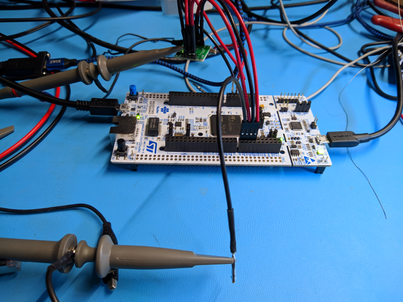
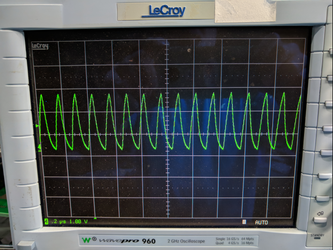
This does not look like a logic signal: the negative excursions make no sense. I suspect you are looking at an unused pin which is capacitively coupled to a pin with a squarewave. |
Beta Was this translation helpful? Give feedback.
-
|
hi peter - agree, it does not look like a logic signal. the same pin (B4) is used for all scope captures. i believe something is going wrong in the tasm function. not sure how to troubleshoot it. i have tried it on another board with the same results the procedure: my guess is that i'm not getting the transfer i intend with the str command
|
Beta Was this translation helpful? Give feedback.
-
|
well, some progress...i can set/reset B4 via inline assembly. still have the issue with unexplained output on the pin when the same code is put in a loop i'm wide open for suggestions this does not work
this works
|
Beta Was this translation helpful? Give feedback.
-
|
On the face of it, that's inexplicable. The only way that differs from the Thumb assembler I've written is its use of constants. I've always passed values as args, or put them in an array and passed the array address. Maybe there's an asm bug involving constants in loops. I'd try passing the various |
Beta Was this translation helpful? Give feedback.
-
|
You could try to add a few NOP()'s after each write to the GPIO register. I recall some problems when writing the SSD1963 driver, partially in assembler code, that I had to add a delay between two statements setting an output high and low. Otherwise it would not change. The IO bus runs at a slower clock than the CPU. So something like: |
Beta Was this translation helpful? Give feedback.
-
|
hi peter and robert same results with passing in stm.GPIOB in r0 and with robert's nop() code above would be interesting if someone else can replicate this thanks, guys |
Beta Was this translation helpful? Give feedback.
-
|
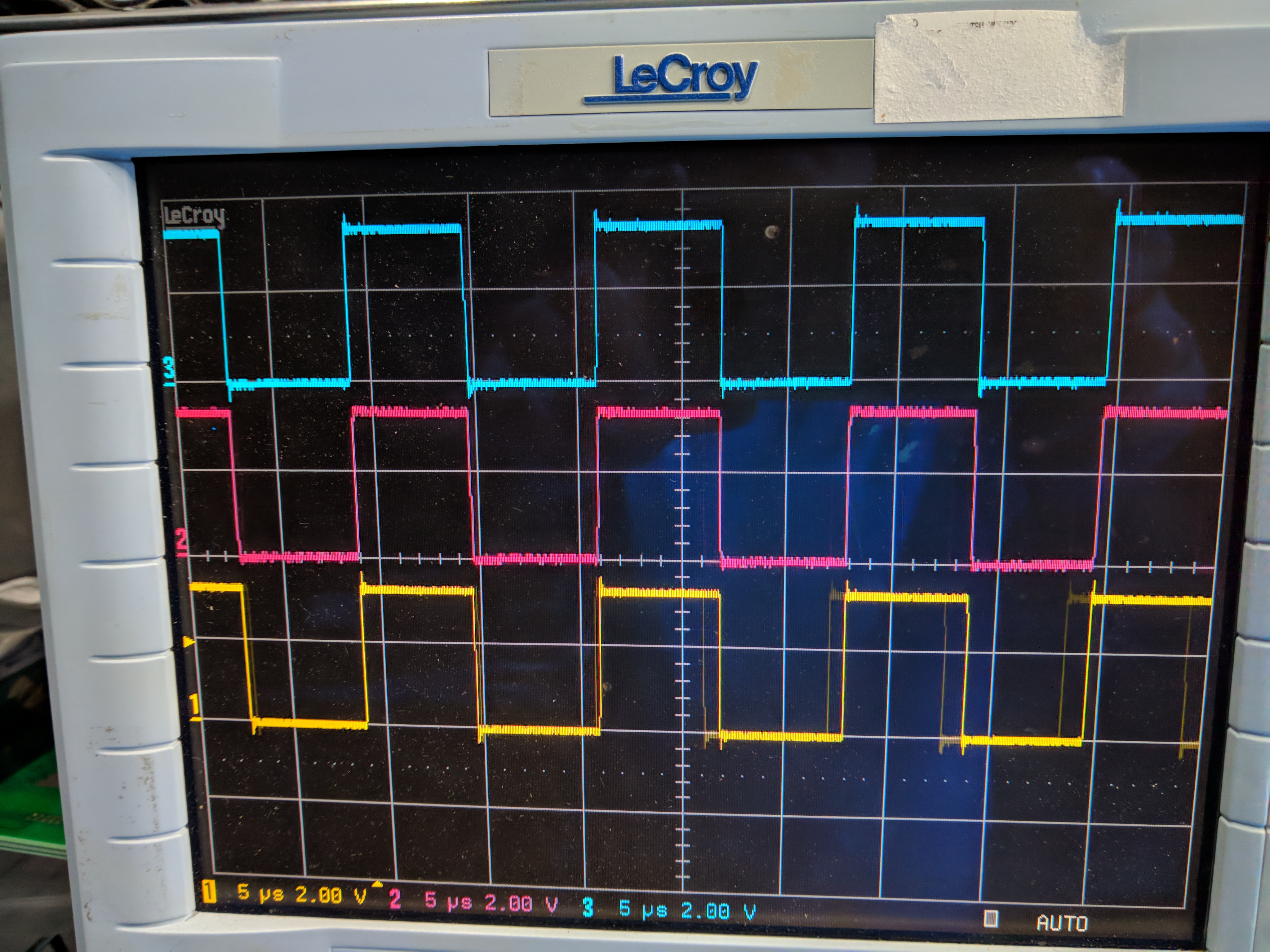
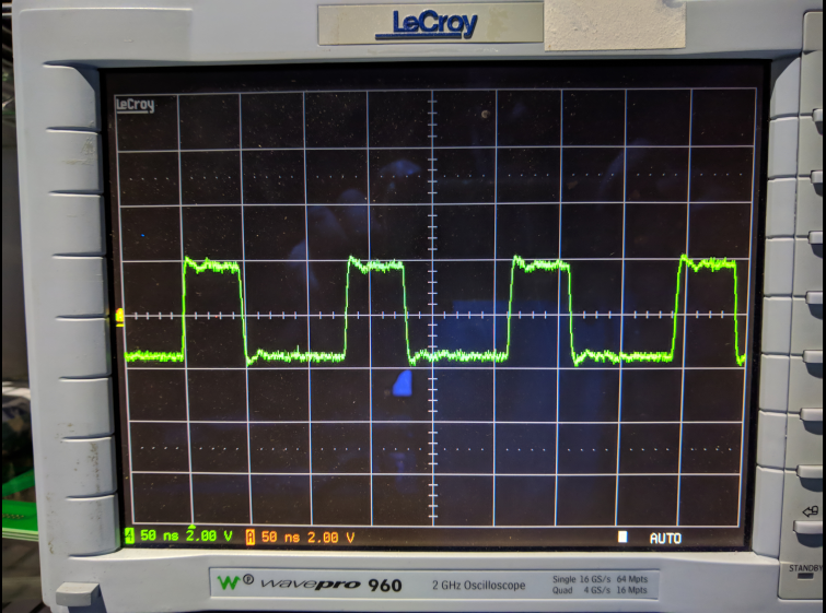
So I hacked together a short piece of code form what I found on my PC for PyBoard: I get the following timings (some ringing on the wire, since I just used the long tip):
|
Beta Was this translation helpful? Give feedback.
-
|
thanks, robert! this works as expected on my end with stm32f407. not a great square wave...tried poking the ospeedr register maybe an stm32f7 issue? same behaviour on f756 and f746. i'll try an f767
|
Beta Was this translation helpful? Give feedback.
-
|
Use the 10:1 mode of your probe for a higher bandwidth, if available. |
Beta Was this translation helpful? Give feedback.
-
|
same behaviour on f767 f407 waveform much better with x10. thanks!
|
Beta Was this translation helpful? Give feedback.
-
|
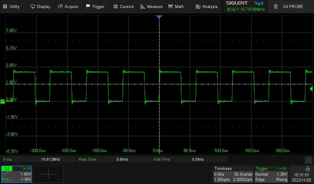
this code that previously was not working is now working on F756 board. main.py was removed. boot.py: can't explain what has happened... peter and robert, thanks for helping previously not working: fast toggle. 100Mhz+:
|
Beta Was this translation helpful? Give feedback.
-
|
Maybe the output speed was missing. Or you did not see it because the probe was set to x1 mode with low bandwidth, giving an Vcc/2 level, and only during the systick interrupt every ms there was time to get to 0 of 3.3V. |
Beta Was this translation helpful? Give feedback.
-
|
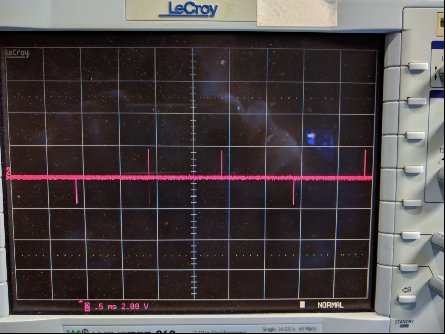
ding.ding.ding. we have a winner moved probe back to 1x and i get the unexpected waveform. i understand the RC filter formed by the probe, but i don't follow how the systick interrupt plays into it. the spikes are every 1ms thank you for looking at this. this was the best i could find for a genuflect emoticon
|

Beta Was this translation helpful? Give feedback.
-
|
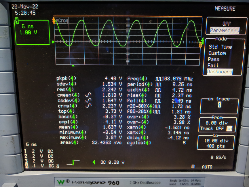
When the systick interrupt executes, the t_asm() function stops, and the GPIO output stays at the value it is at that moment. Since the systick execution time is about 300ns (see the your screenshot above), the voltage at the O-scope input can settle to the GPIO output value. Edit: This means: the code worked all the time. |
Beta Was this translation helpful? Give feedback.
-
|
YES. Always use x10 unless the signal is too small to see properly. |
Beta Was this translation helpful? Give feedback.
Uh oh!
There was an error while loading. Please reload this page.
Uh oh!
There was an error while loading. Please reload this page.
-
tldr:
low scope probe impedance caused mis-identification of high speed waveform
figured out by robert-hh
hello,
trying to toggle pin B4. the functions tpth and tmch work (verified on oscope). tasm does generate some pulses, but not close to what i'd expect. any ideas?
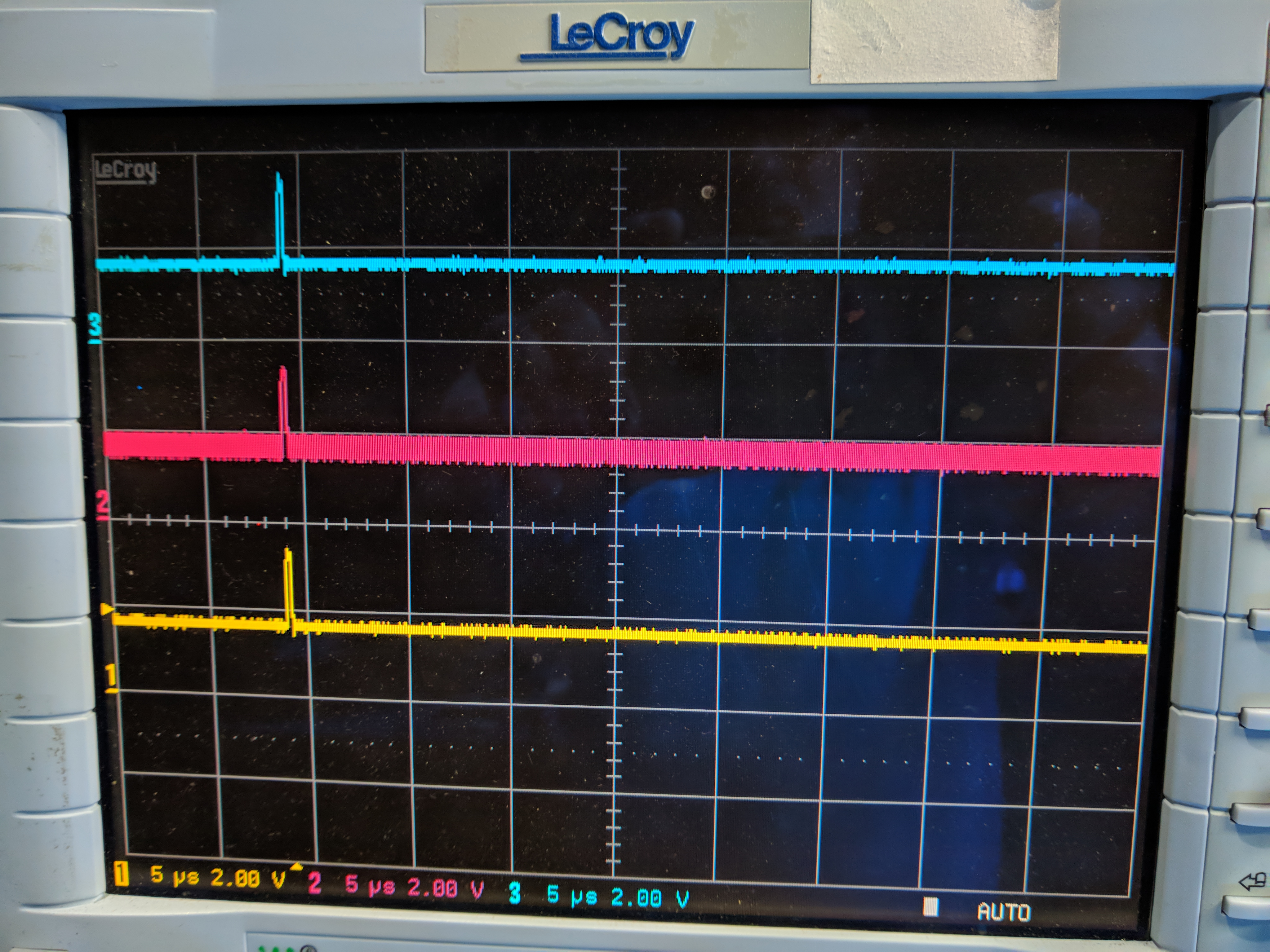
tpth and tmch look like this:
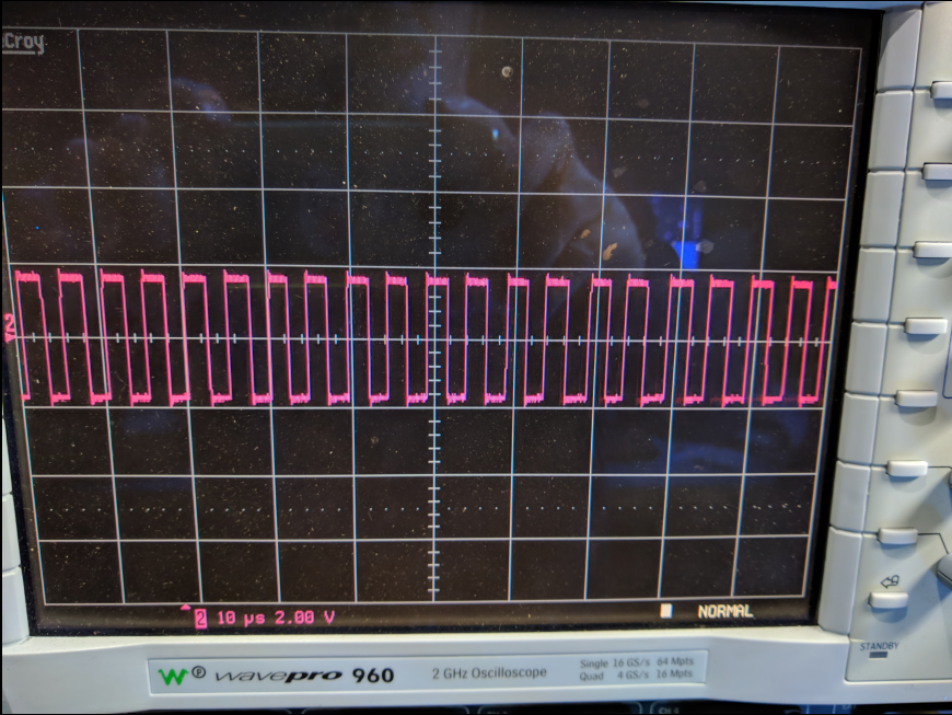
tasm look like this:
Beta Was this translation helpful? Give feedback.
All reactions