Making my own PID library #10180
Replies: 9 comments 22 replies
-
|
Maybe I2C clock stretching causing problems? |
Beta Was this translation helpful? Give feedback.
-
|
Thank you for the reply, I'll have to check with an oscilloscope that but still, if that was the problem, shouldn't it go away after I lowered the clock rate to the bare minimum of 10 kHz? More over, the problem is constantly at the same spot. |
Beta Was this translation helpful? Give feedback.
-
|
Good day, I just checked the SCK signal, everything is the same for both cases (46.8 kHz). Lowered the setpoint to 50 C and the problem is exactly after setpoint. The funny thing is I don"t understand how is the program affecting the input signal (I2C).
|

Beta Was this translation helpful? Give feedback.
-
|
I wonder if it's related to #10067? |
Beta Was this translation helpful? Give feedback.
-
|
Thank you for this link, well the problem is quite interesting. It's not the value of the width of the pulse signal that's the problem. The frequency is. pwm0.freq(30000) By lowering this to let's say 500 Hz the problem goes away. (still present to some degree but not a problem) |
Beta Was this translation helpful? Give feedback.
-
|
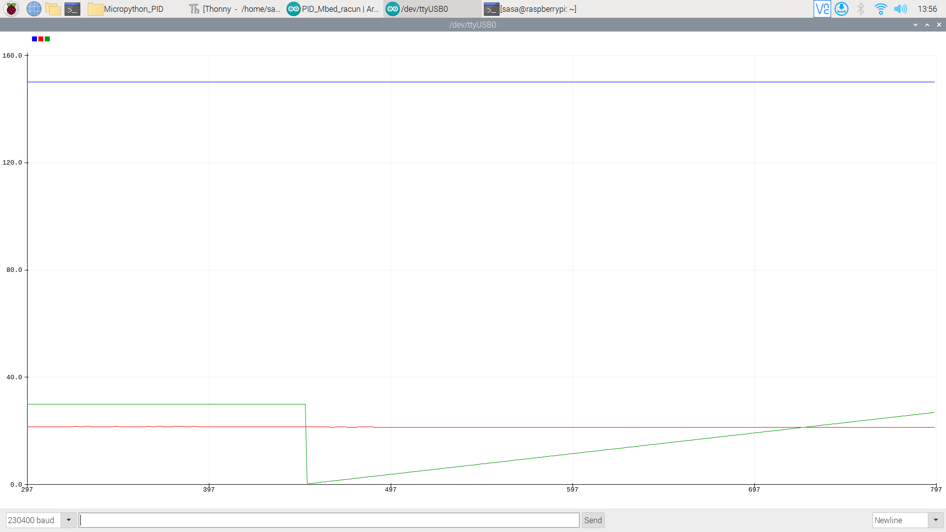
My guess is that this is electrical. Thermocouples are sensitive beasts. On the left hand side of the plot, presumably the PWM is fully on, and at the RHS it is fully off. Only in the transition region around the setpoint is there a pulse waveform. If that can be confirmed with a scope, then the cause is very likely electrical interference between the PWM output and the thermocouple input. |
Beta Was this translation helpful? Give feedback.
-
|
Thank you for this response. You where on the right track, the reason why I did not find the problem is because its not about the PWM value but rather the carrier frequency value that making the problem. pwm0.freq(30000) By lowering this to let's say 500 Hz the problem goes away. (still present to some degree but not a problem) I was trying to lower the pwm value and it would not show any changes. Any recommendation on an article about filtering the PWM signal in a circuit so that it doesn't affect everything else? Thank you once more this helped a lot! |
Beta Was this translation helpful? Give feedback.
-
|
edit: To make conclusions easier You should plot control output not as pwm clock value as (roundPWMOUT = Output / 1000) but
edit: in any problem with performing tuning - let as know, we will help, better explanation of step response tuning method : https://yilinmo.github.io/EE3011/Lec9.html 3.What Do You control ? |
Beta Was this translation helpful? Give feedback.
-
|
I would suggest an electrical solution if it turns out to be an electrical problem. I can make specific recommendations if it is actually electrical. Using code in an attempt to make a silk purse out of a sow's ear seldom turns out well. |
Beta Was this translation helpful? Give feedback.
-
|
You are righ, my sugestion that there is no problem betwen i2c and pwm is false, ( for heater element as actuator i used to use on-off with sub zero hz and there waz no peoblem), but when khz is used in PWM it can cause some issue. |
Beta Was this translation helpful? Give feedback.
-
|
First and foremost, thank you for this much response! I'll start with 2dof. I am interested how did you do a simulation?
Thank you for the very useful links. Yes, the parameters where made using Ziegler-Nichols step response method using a RPi 4. As for the heater, I am controlling a small DC heating PTC element in aluminum case. I think that would make it a second order process because the heater has where to store energy? This is something that I wanted to ask somebody about sampling time. Is it mentioned somewhere in the lings the calculation that you gave? I have come across this formula also Tsample = Tprocess/( 5 to 10) ??? I will be posting more pictures about the project here. Thank you so much for your time! |
Beta Was this translation helpful? Give feedback.
-
|
Here is a quick hand drawn schematic.
As peterhinch mentioned above, yes the problem is electrical. The PWM signal is affecting the K-type thermocouple. What would be easiest way to resolve this? I would still like to have a higher frequency than 500 Hz for the sake of resolution in control. |

Beta Was this translation helpful? Give feedback.
-
|
to answer Your question in some ordered manner due to more important issues:
-> because You use PWM on 30000 (or 10K or just in some kHz ) so wires of pwm can act like Radio and wires of Termo can act like recewier ( but ussualy sensor with cables is shilded) so maby interference is with sda-scl communication .... issue to investgate for You, but before that:
Now You have "resolution in control set by -> time.sleep(0.1) because You update control value every 0.1 sec (10 Hz) ( in real: 0.1s + time of code execution time (which we can ignore ) not 500 Hz or not PWM freq like 10kHz or 30kHz . The 0.1 sec is a Sampling (Ts) time here. Now: "SAMPLNG" Time " : I give Tsample = Tprocess/( 5 to 10) i.e sampling frequency should be at lest 5 to 10 faster than process time ( sugested by control process book therory based on Nyquist theory from signal processing. You can sample signal for Your 500 Hz it will still good but when Your process reaction takes seconds it is beter consider if is is worth (from CPU, other task in your code point of view). of corse the higher Fs (1/Ts) then we consider our controler more as "analog" and less as digital controller and we do not have to play in discretization of PID. HOW to solve electrical issue? first try some experiments ( to analyse of nature of noise source) . edit: thy also some PWM ramp ( generate for example from 0 to 20% in 5 sec ) to analyse of temp error propagation ) |
Beta Was this translation helpful? Give feedback.
-
Bye default i consider your process as first order with delay , it also be considered as higer order it depends of physical construction, by default first order for Your is good ( see https://www.electricalengineeringinfo.com/2017/05/transfer-function-mathematical-model-thermal-system.html ) about my "stupid" simulation: I just done a step response of Your PID controller - Your code but with: Setpoint and Input fixed values (no sensor reading), (at first I was supriced that control signal is saturated also "donky blinded" by "lack of" sampling time and just not even noticed a transient behavior ( electric issue noticed by pererhinch) which is most importnant issue. In typical numerical simulation i usually use from odeint (from scipy.integrate python ) with digital controllers implementation ), when numerical proces identification is needed then I use mentioned z Ziegler–Nichols for first order or scipy.optimize lib for more advanced. |
Beta Was this translation helpful? Give feedback.
-
|
@ajevticc i have coded simple process simpulation for Your PID implementation (with some changes according do anti-windup section), as example I added tutning based of IMC rules (for Your pid code) and ziegler step method ( standard pid implementation), |
Beta Was this translation helpful? Give feedback.
-
|
@2dof thank you so much for the response. For the last two weeks I have been unwell and therefore unable to respond at all. I want you to know that I really appreciate your help. I hope to get back tomorrow to the laboratory and start testing the code, and finally to show the improved setup. Likewise, I am reading for now... |
Beta Was this translation helpful? Give feedback.
-
|
Hello @2dof, tried to running your simple_pid_FOPDT.py, but it just shows three windows and then reports a crash? I am using Thonny and Python 3.10.6. |
Beta Was this translation helpful? Give feedback.
-
|
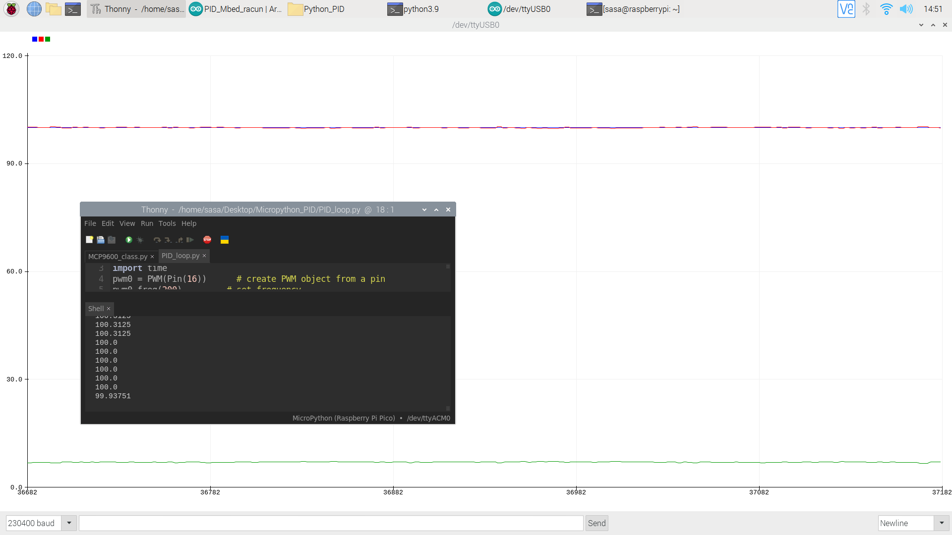
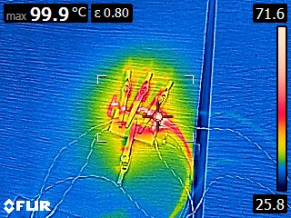
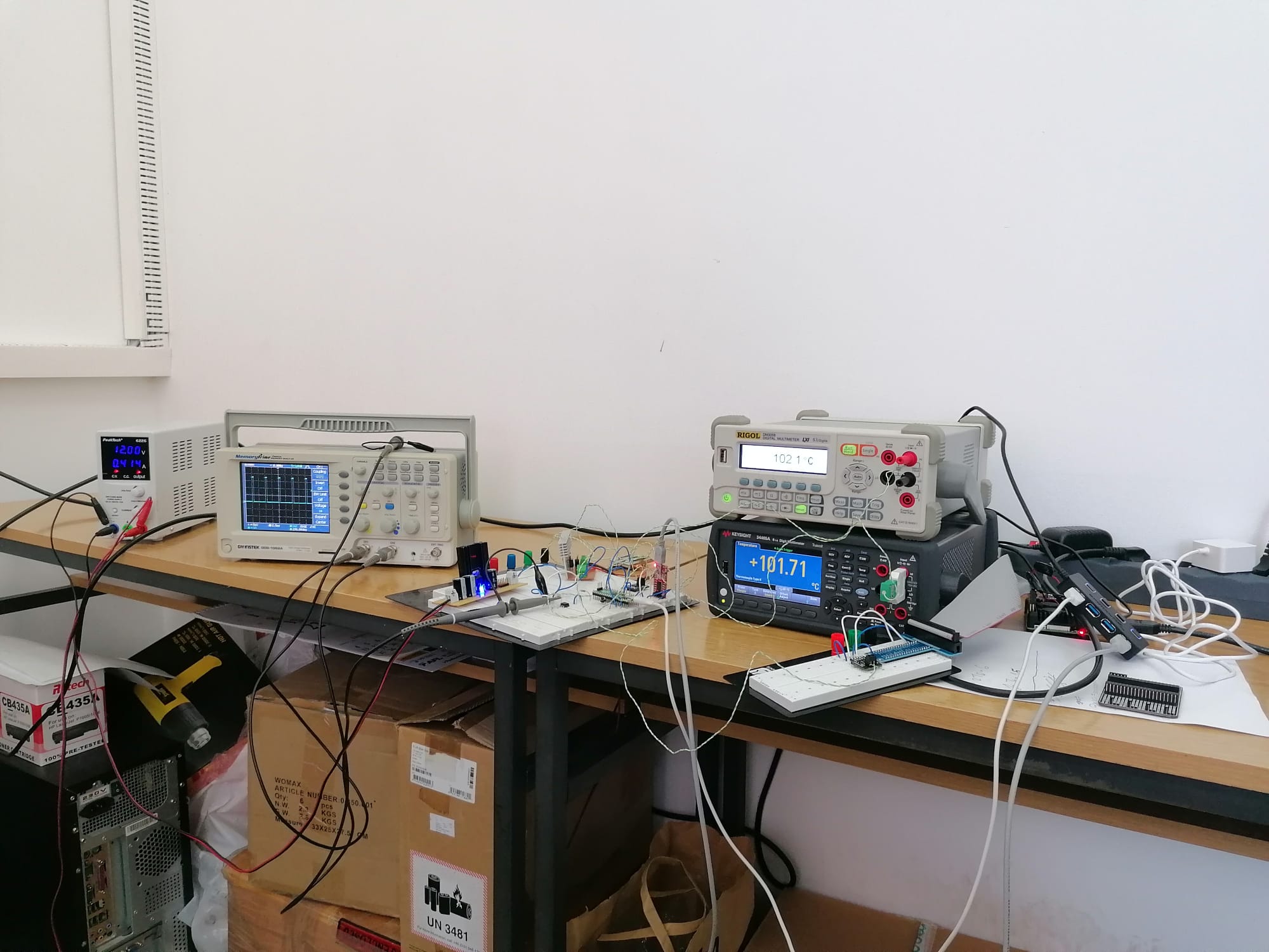
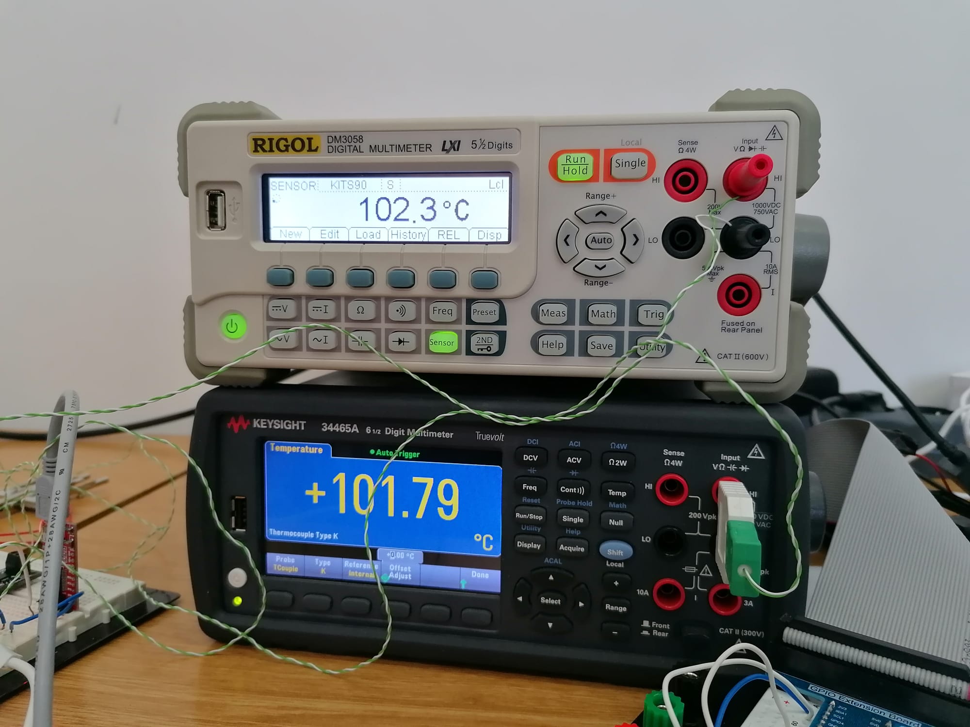
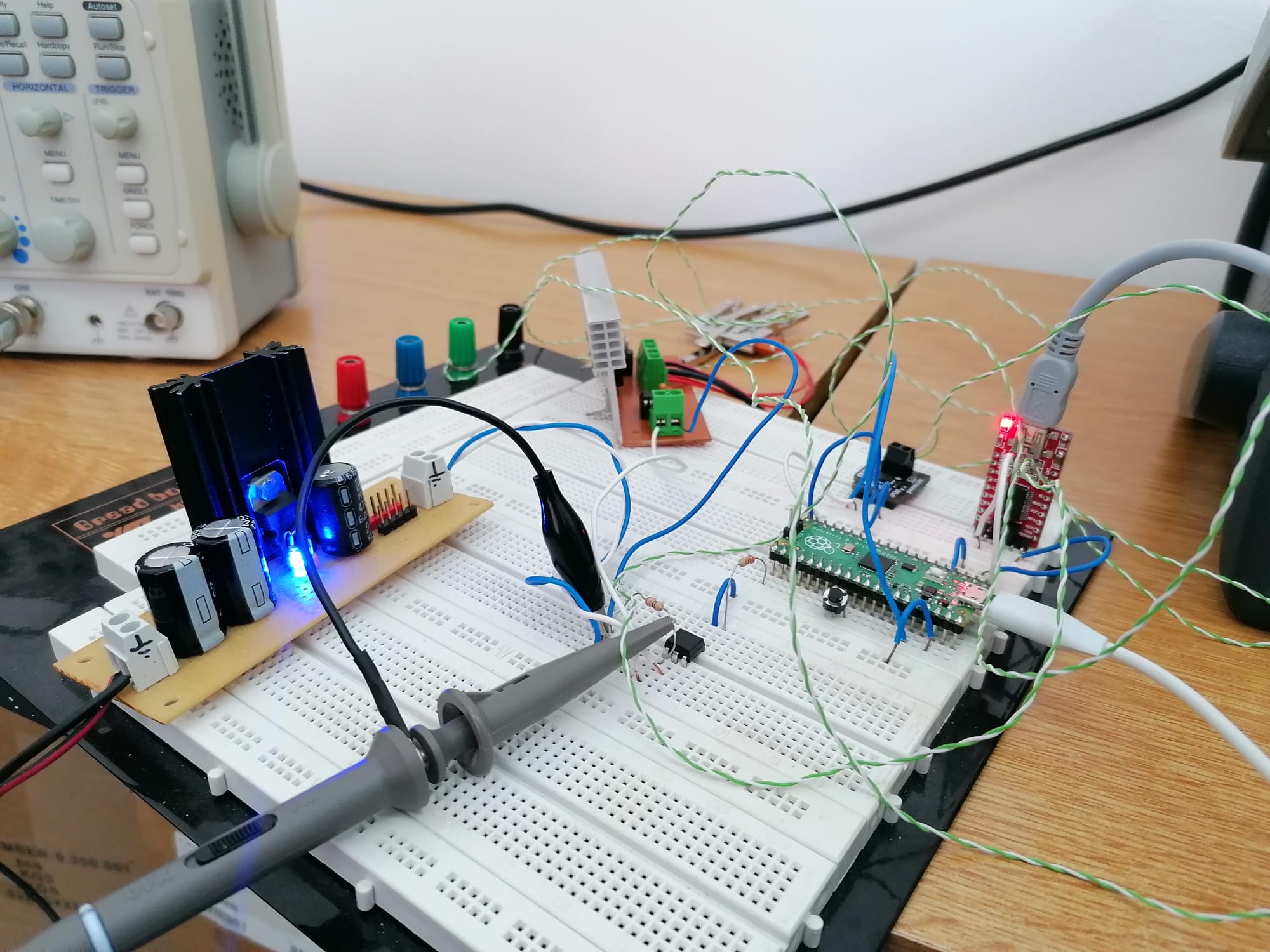
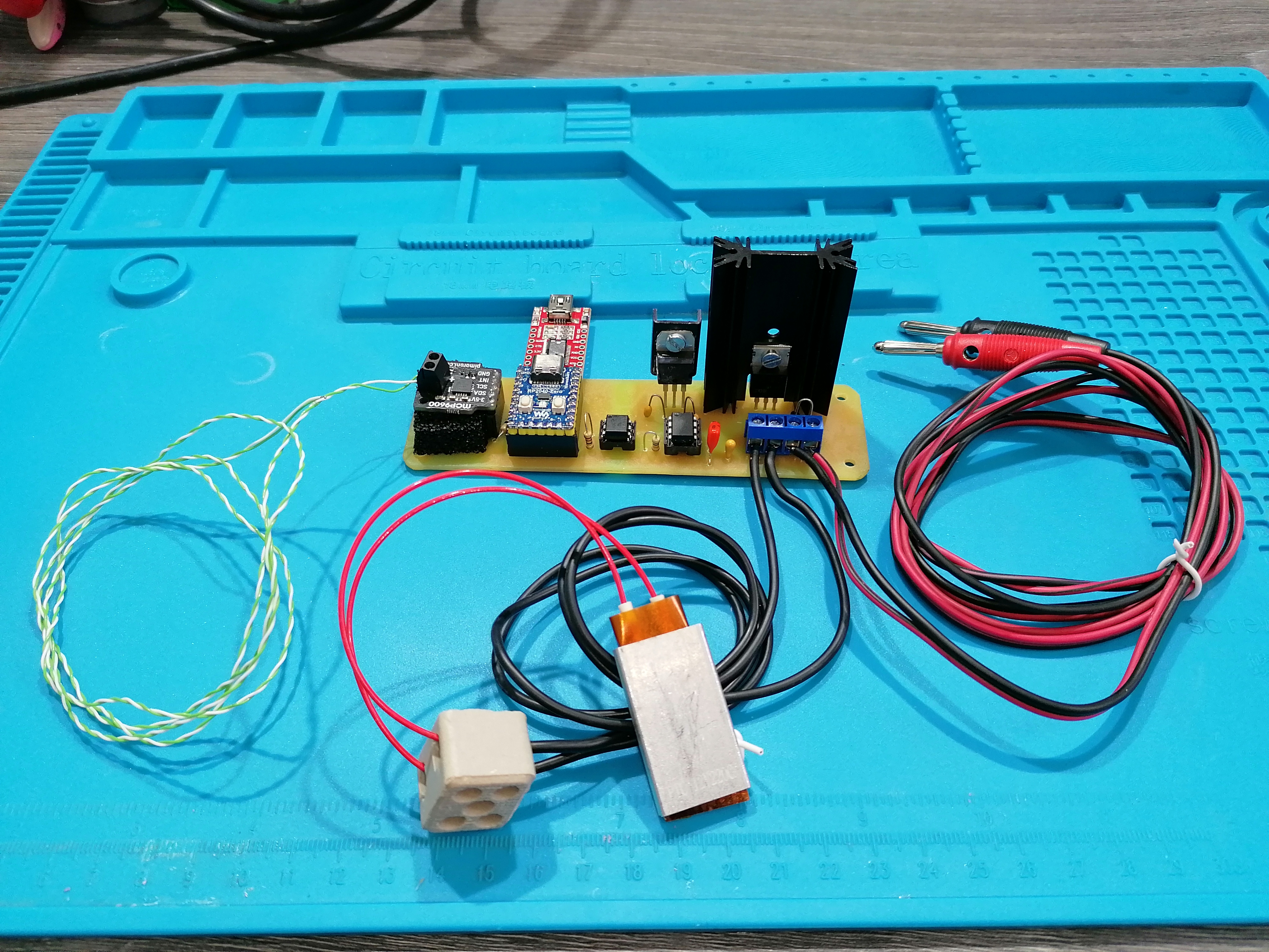
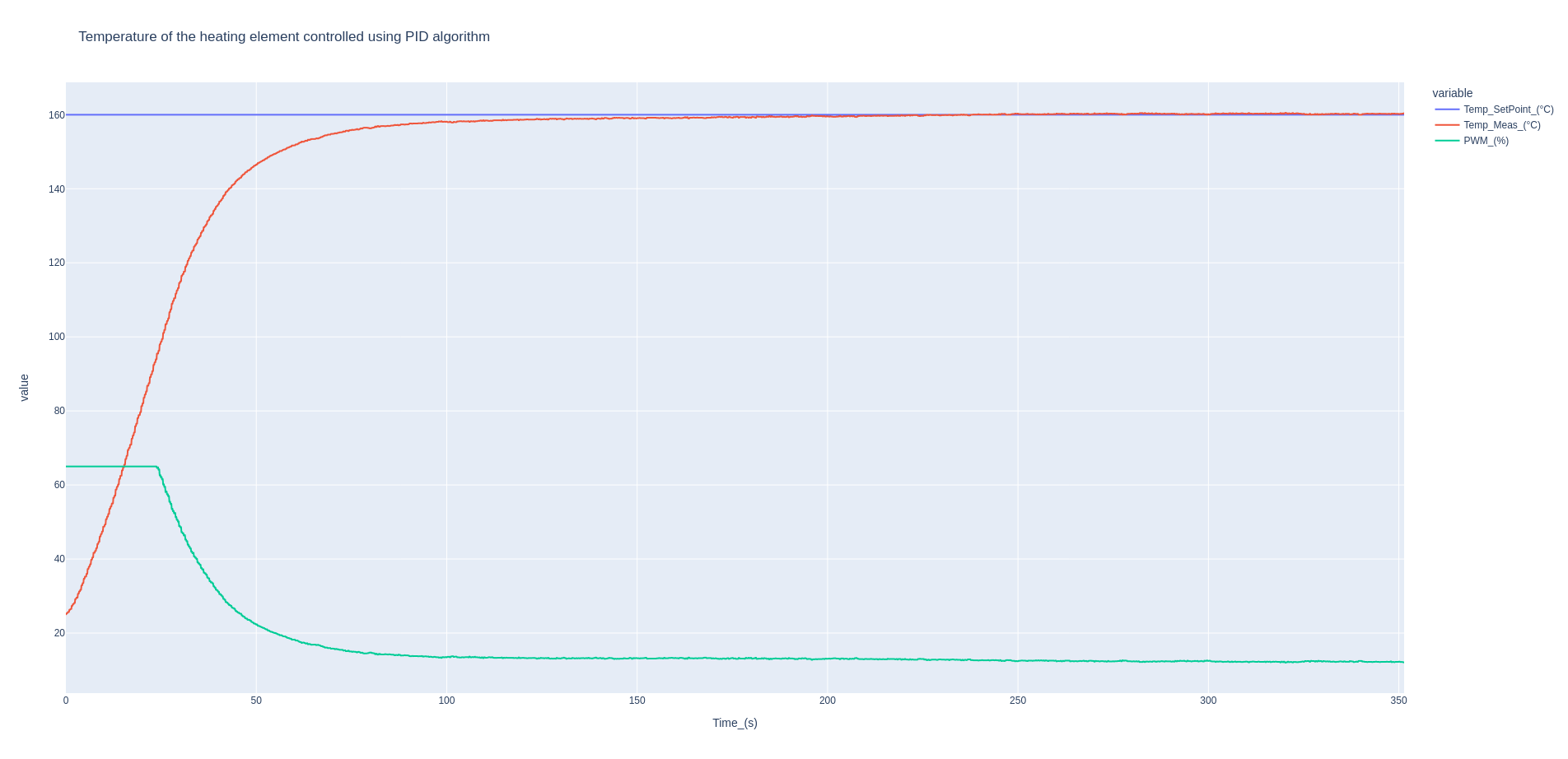
Time to show the setup. I solved the problem by putting an optocoupler in between the Pi Pico PWM output and the input of the TC 427. By doing this, I have separated the noisy switching GND entirely from the Pi Pico and the thermocouple. Also, shortening the PWM line and by that lowering the inductance of the trace (no ringing on the PWM line). As for the integral windup, one of the ways to solve it was also to make the Ki constant small in retrospect to the Kp component of the PID. My initial parameters were Kp = 0.1, Ki = 6.0 and Kd = 1.5. When I made the Kp much larger, like Kp = 1000 and Ki = 1.6, the system started behaving as expected with no overshoot. Here are some pictures at 100 C.
|
Beta Was this translation helpful? Give feedback.
-
|
|
Beta Was this translation helpful? Give feedback.
-
|
Good work. My control system theory is decidedly rusty and I'm happy to be told that the following is nonsense but I'll stick my neck out anyway... As has been mentioned above, heating a thermal mass approximates to a single pole system. Say your control system has a large proportional (P) term, and zero integral (I) and derivative (D) terms. On power up it will approach the setpoint on an exponential curve, stabilising at the setpoint with no overshoot. It sounds to me as if this is very nearly what you have, although you haven't mentioned D. Clearly this behaviour can be improved, but the question arises as to what needs to be bettered? The time from power up to getting within a given tolerance of the setpoint or the response to external disruption when the setpoint is reached? If the former you can use a nonlinear approach: turn the PWM to 100% until within tolerance, then switch to P==1000. That achieves the fastest possible outcome. It's really only in the case where you need a rapid response to external disturbances that you need optimised PID control. |
Beta Was this translation helpful? Give feedback.
-
|
Good job with solving problems. To test setup (one or both PID architecture You can put some ice/ cold air) check difference). I recommend the books as additional lecture:
|
Beta Was this translation helpful? Give feedback.
-
|
@peterhinch yes, I have forgot to mention the D parameter. To avoid the derivative kick I have kept the Kd = 1.0 also very small compared to Kp and Ki. You are completely right, everything is a trade-off. For me personally, two things were important: |
Beta Was this translation helpful? Give feedback.
-
|
@2dof yes that is also one of the problems that I had to solve early on. Tho avoid the derivative kick due to noise but still to retain the computational speed I did not implement a software filter directly into the code loop but at the hardware, MCP9600 has a filter that you can set on. And it works very nicely. Also keeping the Kd very small in comparison to the Kp and Ki. For the testing to outside interference I use compressed air and the system is behaving very good. Just to check with you, you want me to test if the time for processing the PID values is stable (not including uart and etc.)? Yes as I mentioned above, everything is a trade off. Thank you so much for the literature, that is something that I also wanted to ask about but forgot. Will be reading it. Wanted also just to ask you again about the your simple_pid_FOPDT.py, it just shows three windows and then reports a crash when i try to run it. I am using Thonny and Python 3.10.6. |
Beta Was this translation helpful? Give feedback.
-
|
about simulation simple_pid_FOPDT.py: About noise filtering, if needed use MCP biuld in filtering, if You want use software filter directly then micropython is not to fast ( usually for dsp filters arrays are used, arrays object in micropython are slow. But usually as noise filters in control a lag function is added ( just first order transfer function ( F(s)=1/(1+T_lag *s) where (...) higher frequency fluctuations in the process variable Alternative for noise filtering You can use a control u = P+I+D + alpha* du(t)/dt , where <alpha* du(t)/dt> is optional derivative filter , but all depends of Your goal - I usually use "the simpler, the better" rule. About sampling Time/ processing Time: Your Code (reading sensors, pid value calculation and sending to uart) is much faster than sampling time ( defined by time.sleep(0.1)) so You do not have take account processing time. But when You do a lot of calculation in while loop (other stuff than PID calculation) You can take exact time using utime module ( also, You can use to measure time execution of Your code) . In Your case it is not need be implemented, but always good to know: About control tolerance: In some process You need go as fast as possible to the setpoint but avoid overshoot then "penalty" cab be added ( when we have overshoot then u=u- beta*error) , do You add non-linear element in Your control. But usually a some optimal control design is enough. |
Beta Was this translation helpful? Give feedback.
-
|
This is the fully functional version of code. from machine import Pin, I2C, PWM, UART
import time
pwm0 = PWM(Pin(8)) # create PWM object from a pin
pwm0.freq(200) # set frequency
i2c1 = machine.I2C(1, sda=Pin(14), scl=Pin(15), freq=50000) #Error 5 change CLK speed
#or wrog value CLK
Setpoint = 180.0
#Original param
# Kp = 0.10
# Ki = 6.0
# Kd = 1.50
Kp = 1000.0
Ki = 10.60
Kd = 1.0
outMin = 0.0
outMax = 65000.0
IoutMin = -65000.0
IoutMax = 65000.0
dt =0.1
Iout = 0.0
Input = 0.0
lastinput = 0.0
uart = UART(0, baudrate=230400, tx=Pin(0), rx=Pin(1))
i2c1.writeto_mem(0b01100110, 0x06, bytearray(0x20))
i2c1.writeto_mem(0b01100110, 0x05, bytearray(0x04))
valueK = [0x00,0x00]
temperatureK = []
while True:
valueK = i2c1.readfrom_mem(0b01100110, 0x00, 2)
temperatureK = (valueK[0] * 16.0 + valueK[1] /16.0)
Input = temperatureK
error = Setpoint - Input
Pout = Kp * error
Iout = Iout + (Ki * error * dt)
    if (Iout > IoutMax):
        Iout = IoutMax
    if (Iout <= IoutMin):
        Iout = IoutMin
Dout = ((Input - lastinput ) /dt)
Dout = Kd * Dout
Output = Pout + Iout + Dout
if (Output > outMax):
Output = outMax
Iout = Iout - (Ki * error * dt) # anti-reset windup
if (Output <= outMin):
Output = outMin
Iout = Iout - (Ki * error * dt) # anti-reset windup
PWMOUT = int(Output)
pwm0.duty_u16(PWMOUT)
roundPWMOUT = Output / 1000
strPWMOUT = str(roundPWMOUT)
strSETPOINT = str(Setpoint)
strINPUT = str(Input)
uart.write(strSETPOINT+' '+strINPUT+' '+ strPWMOUT +'\n')
lastinput = Input
print(Input)
time.sleep(0.1) |
Beta Was this translation helpful? Give feedback.
-
|
Yo do not ned use: since You have saturation checking in output calculation (and add antiwindup component to Iout part. |
Beta Was this translation helpful? Give feedback.
-
|
Note that saturation checks can be a one-liner: value = max(min_val, min(max_val, value)) |
Beta Was this translation helpful? Give feedback.
-
|
I hope you don't mind my asking a probably silly question; I am new to micropython. I see you use 'from machine import uart', but following this guide from AdaFruit, there is no such library called 'machine' either built in to MicroPython or in the MicroPython library bundle, and anyway the name seems to suggest the implementation is interchangeable so that you have a different one per board. So how did you get the uart library installed for use in MicroPython? |
Beta Was this translation helpful? Give feedback.
-
|
This forum is about MicroPython, not Adafruit CircuitPython. There are quite a few differences between them, even if both use the same Python core engine maintained my MicroPython. MicroPython usually has a built-in machine module with several classes. One of the is teh UART class. See https://docs.micropython.org/en/latest/library/machine.html#module-machine |
Beta Was this translation helpful? Give feedback.
-
|
Hello everyone, long time no see! |

Beta Was this translation helpful? Give feedback.
Uh oh!
There was an error while loading. Please reload this page.
-
Hello everyone, I am trying to make a simple PID controller for a heater using MicroPython, Pi Pico and a MCP9600 Thermocouple Reader.
I have based it around the standard PID Arduino Library(http://brettbeauregard.com/blog/2011/04/improving-the-beginners-pid-introduction/), which is also used for MicroPython simple-pid library (https://micropython-simple-pid.readthedocs.io/en/latest/#), (https://github.com/gastmaier/micropython-simple-pid/blob/master/simple_pid/PID.py#:~:text=%23%20Compute%20integral%20and%20derivative%20terms,output%2C%20self.output_limits)).
Now, the main problem that I have is quite interesting.
Until the circuit reaches the desired Setpoint (100 C), the program and the I2C bus work just fine. The moment that the Setpoint is overshoot, the readings of the temperature go all over the place (random values all of a sudden). I have tried multithreading, longer delays, lowering the I2C clock but nothing helps to make the problem go away. At the end I am printing the data via UART and using a FTDI chip just for an easier display on the Arduino Ploter (you can see on the screen shoot the behaviour of the input (red), output (green) and setpoint (blue)).
Here is the code:
All ideas are welcome, my only guess is that somehow the math of the program is interfering with the I2C bus (input)?
Thank you so much for your time reading this!
Beta Was this translation helpful? Give feedback.
All reactions