Micropython ADC Noisier than Arduino on ESP32 #9227
-
|
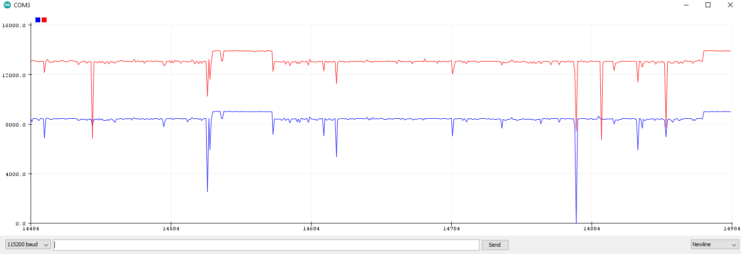
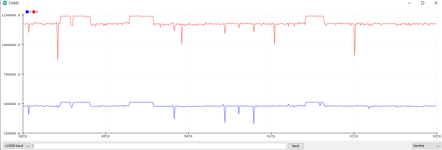
So I'm somewhat new to Micropython and I am not sure exactly what I am doing wrong here. The current setup is that I have a motor making clean sine waves onto an encoder and the encoder is giving me an analog signal that I need to read with my ESP32. I've noticed that the signal is noisier than I had hoped, but I thought it might have been just the hardware. I then tested the exact same hardware with Arduino code but got a significantly cleaner signal. Here is the code and results of Micropython : Signal: Here is the Arduino code: Signal: Since the hardware setup is exactly the same, I must have messed up the code for the Micropython. Any suggestions? |


Beta Was this translation helpful? Give feedback.
Replies: 10 comments 13 replies
-
|
I notice that with the Micropython code that the input signals are about 10 times higher. These signals come from the encoder so how do they change level? I.E. what is the encoder source impedance? |
Beta Was this translation helpful? Give feedback.
-
|
Based on the documentation, it looks like the read_u16 scales it up from the esp32 native 12 bit adc to a 16 bit with a range of 0 ... 65535. I mainly used read_u16 because it was the first option in the documentation. Arduino I'm guessing doesn't scale the adc values. In terms of the impedance, ummm I'm not sure how to measure that? There's about a 51k ohms or resistance between the signal and ground of the encoder, is that what you're asking? |
Beta Was this translation helpful? Give feedback.
-
|
Not merely are your results a different scale vertically, but the ESP32 seems to be recording the red trace with a period of roughly 27 ms (if that's the horizontal time unit) while the Arduino records the same period as around 100 ms. |
Beta Was this translation helpful? Give feedback.
-
|
Gotcha, so I should try using the read_uv() function instead? I'll try switching it and get back to you on that. The plot I used is from the Arduino IDE so the time scale is simply whenever it prints out the values. I did not add any delay to the code so it just means that the Arduino code ran faster than the micropython for this test. So those time units aren't accurate at the moment. |
Beta Was this translation helpful? Give feedback.
-
|
I tired with read_uv but the values seem even bigger than read_u16 and it didn't solve the problem |
Beta Was this translation helpful? Give feedback.
-
|
Just for reference, this is the only change I did in the code: |
Beta Was this translation helpful? Give feedback.
-
|
Are those waveforms actual measurements or simulations? I don't understand how the levels could be different unless the ESP32 ADC is being setup differently between Arduino and Micropython |
Beta Was this translation helpful? Give feedback.
-
|
These are actual measurements and I also agree that I must have set up something different between the Arduino and Micropython but I just cannot think of anything. I literally flash a brand new esp32 with the latest micropython: https://micropython.org/download/esp32/ (version 1.19.1) ran the code above with the encoder and got that signal. I replace it with Arduino selected onto "ESP32 Dev Module" board upload the above code and it produces clean signals from the encoder. |
Beta Was this translation helpful? Give feedback.
-
|
Is the encoder being driven by the ESP32 as well? Break the connection between the encoder and the ESP32s ADC to verify that the noise is coming from the encoder. I was focusing on the ADC input creating the noise. |
Beta Was this translation helpful? Give feedback.
-
|
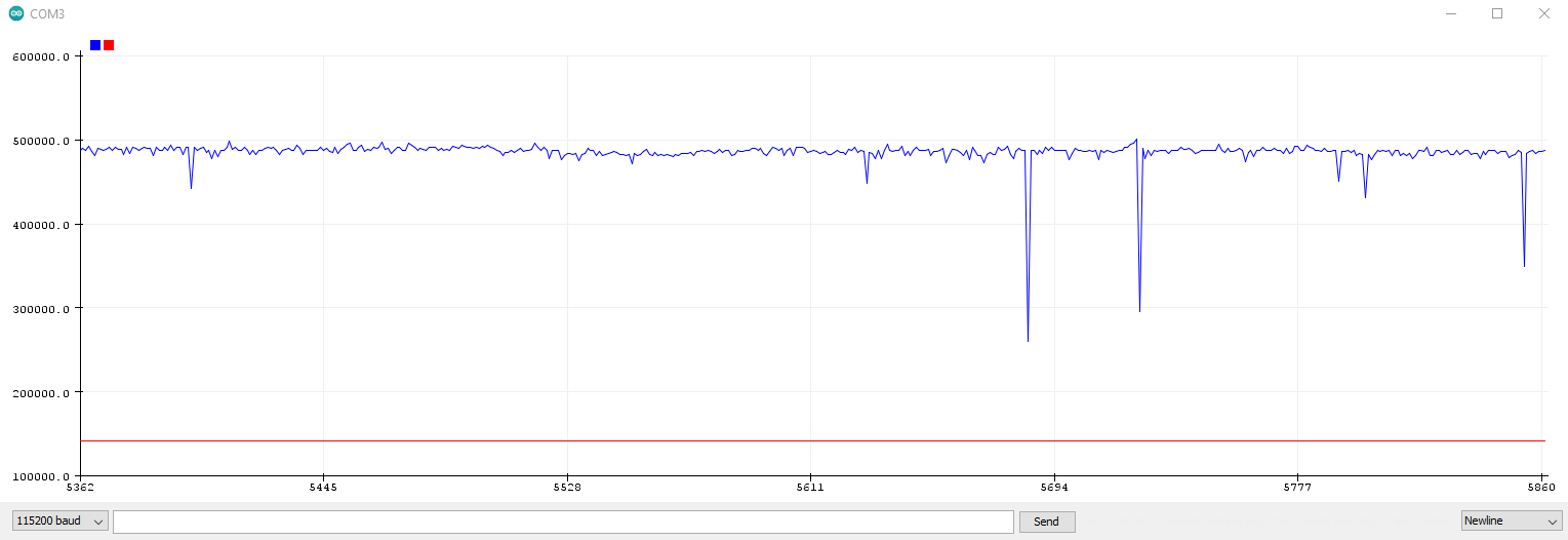
No, I have a separate system entirely for controlling the motor and they are not connected at all. When I unplug one of the pins of the encoder, then yes that signal is clean: |
Beta Was this translation helpful? Give feedback.
-
|
@stoplime Can you tell us more about how you generated the "constant" waveform. What's connected to the pin while you're measuring that? It's really interesting that the glitches are perfectly correlated on both inputs. FWIW, I tried to reproduce this here with a sine wave from the signal generator but wasn't able to see the glitches. Out of curiousity, what's the frequency of the motor sinusoids? (@scruss Frustratingly the arduino plotter's x axis is sample-number, not time). In general the ESP32 (and especially MicroPython on the ESP32) is not particularly well suited to this sort of task because you will end up with a large amount of jitter in your sampling. Behind the scenes MicroPython is running in a FreeRTOS task and getting given little slices of CPU time. Your samples are not evenly spaced in time. This doesn't explain why you see these sharp drops though...something else is going on there. |
Beta Was this translation helpful? Give feedback.
-
|
The "constant" is just the encoder running without the motor being on and the table is still. You state that the ESP32 is not ideal for reading ADC? so what would exactly and also within the same price range and ideally smaller form factor? Eventually, I'd like multiple of these connected with SPI and sending the data to a master device. I just choose the ESP32 because it had a 12bit ADC and is very cheap. |
Beta Was this translation helpful? Give feedback.
-
|
What are you using for an encoder? So, that I can understand why an ADC is involved. |
Beta Was this translation helpful? Give feedback.
-
|
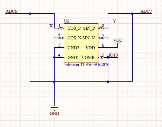
I actually have two encoders connected but the graph only shows one of the sine and cosine. The one shown is an infrared LED with a photoresist pair with a disk filled with slots. The other not shown encoder is this product: https://www.mouser.com/ProductDetail/Infineon-Technologies/TLE5009-E2010?qs=%252BWnEOWq1JvGhyLjFifYi7Q%3D%3D Here is the diagram for the TLE5009: VCC is connected to the 3.3v pin of the ESP32. This is all powered by USB. Here is the result with all the signals: |

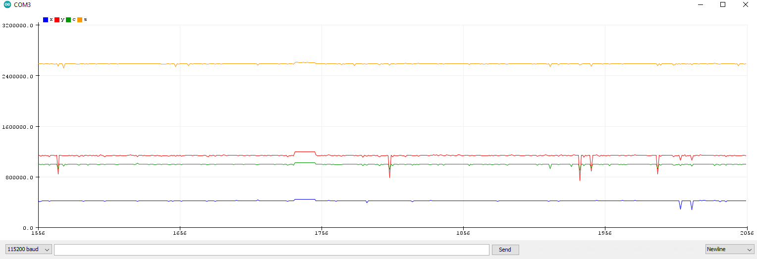
Beta Was this translation helpful? Give feedback.
-
|
Oh and one more thing, I added a decoupled capacitor of 10uF between the 3.3v and ground somewhat close to the LEDs before the potentiometers. |
Beta Was this translation helpful? Give feedback.
-
These two facts seem to point to an external electrical source of interference which is being coupled into both signals. For good ADC results you need a low impedance circuit and you need to ensure that the signal is arranged to match the ADC sensitivity. In other words, the signal minimum should result in an ADC value close to 0, and the maximum should produce something close to full scale. Meeting these requirements can involve using an op-amp for gain, level shifting and impedance reduction.
Quite. A schematic would help. |
Beta Was this translation helpful? Give feedback.
-
|
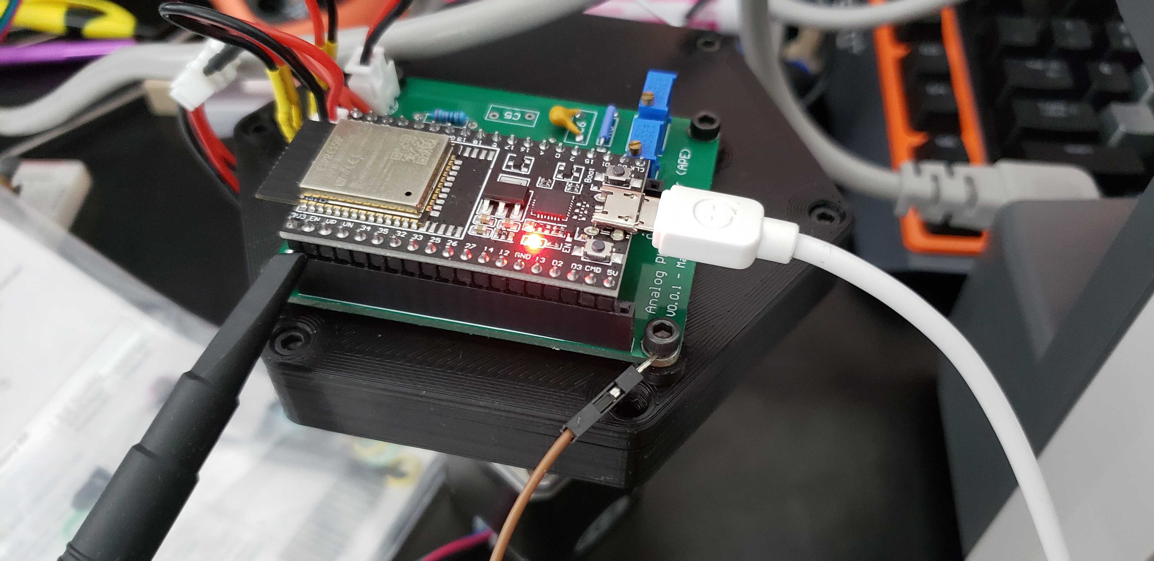
I was planning on eventually tuning the signal better to fit the range of the ADC but this was merely an early prototype to see what the signals would look like. I was mainly taken aback by how the noise differs so much between the Arduino implementation vs the Micropython implementation whiles using the same hardware. I've had issues before where I just didn't read the documentation very well and saw that I needed to change the attenuation settings for the Micropython to read the signals above 1V but I haven't seen any leads to how to fix this issue so far. The main reason I excluded the diagram and motor was that I was able to get clean signals with the Arduino, I didn't think that the hardware was the problem. Here is the full setup I have:
Basically, the breadboard on the left just controls the motors and is not connected to the ESP32 in any way other than through the motor. I am using a Teensy to control a TMC2225 to run the motors and that is being powered by a 12v supply. The Encoder is mounted to a 51:1 gear reduction on the motor end just for testing purposes to see very small changes. I soldered JST connectors to the LEDs and photoresistors which connect to a custom board that had potential slots for extra resistors and capacitors if I needed them but for now, I just bridged most of them to get the simple diagram you see above. The ESP32 is only powered through the USB cable connected to my computer and supplies the rest of the board with 3.3v. The main reason I ordered a custom board for a prototype was that I thought I couldn't get a good stable mount for the TLE5009 since it was a surface component. This way I was able to 3D print a mount for the board with screws and the TLE is just soldered onto it and is very stable. I know the board is in no way a good design atm but currently just a mount for all the components. |


Beta Was this translation helpful? Give feedback.
-
|
So I got an oscilloscope to measure the signals, and I hooked it directly to 3.3V source and I was able to spot the noise. |
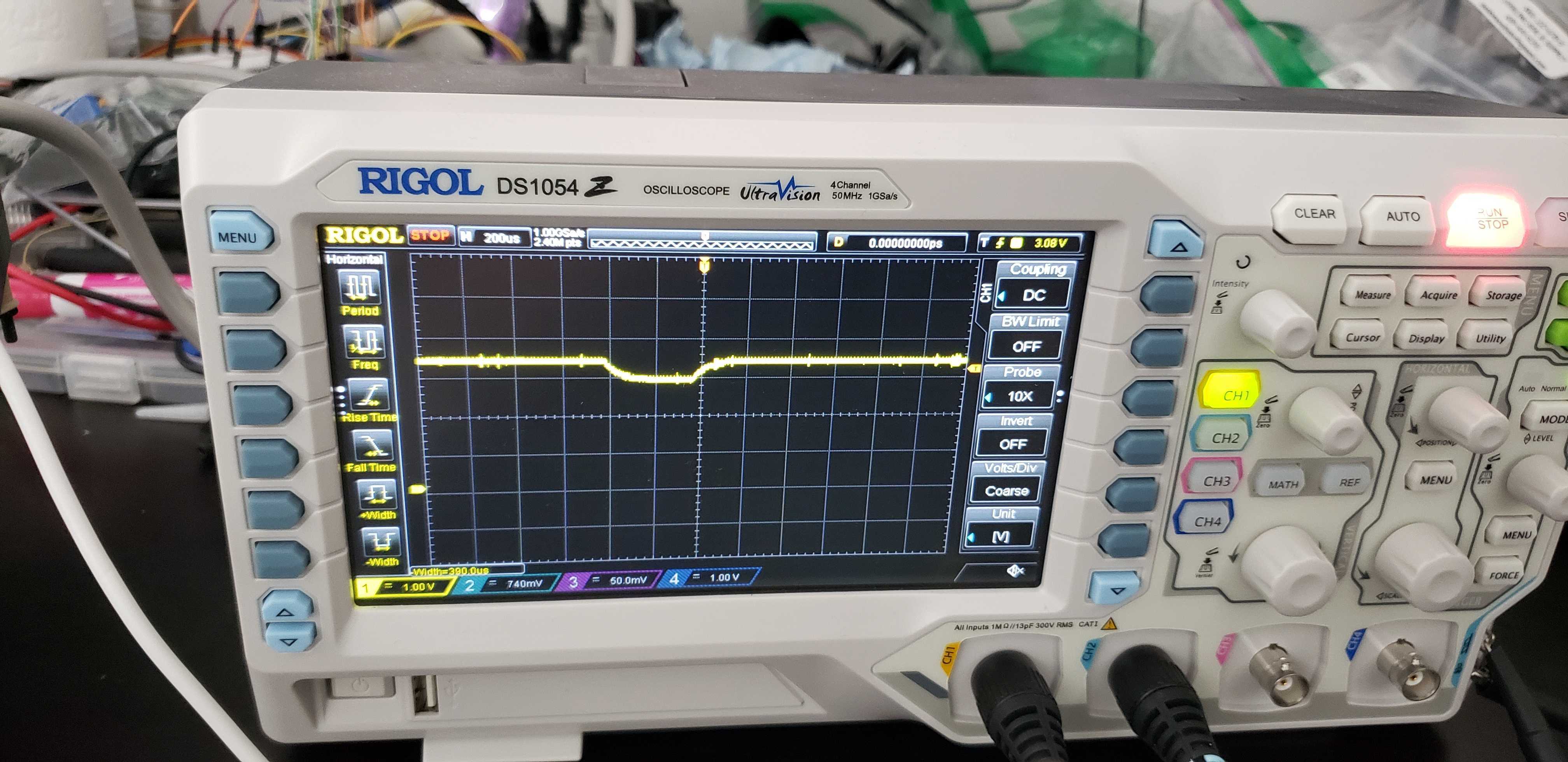
Beta Was this translation helpful? Give feedback.
-
|
Two hardware issues with the 3V3 regulator on these boards ... the AMS1117 has been a suspect part for being able to handle the current required by WiFi. If you don't see that voltage drop running Arduino then it suggests to me that Arduino handles the start-up condition of the WiFi better. Run a test where you just boot to a state before any WiFi is activated and compare Arduino with Micropython. I have been in the habit of putting 1000uF on the 3V3 pin. Also, there are lots of threads on poor USB supplies and cables, but that shouldn't be your problem. I also often even up putting 1000uF on the 5V pin as well. Does D1 and Q1 have the linearity that you require? |
Beta Was this translation helpful? Give feedback.
-
|
Yes, I've Isolated the problem being the WiFI causing voltage drops on the supply! Man, now I'm just facepalming myself knowing that I've been connecting to webrepl this whole time to be able to send commands and read the plot using the Arduino IDE at the same time. Honestly, I thought I was being clever using webrepl in that way but forgot to mention it here. Once I disable the wifi and send commands through tera term, the noise went away. This was hard to see without an oscilloscope though since I couldn't plot it using the Arduino IDE whiles tera term has access to the port. So what you're saying is that if I were to place a 1000uF capacitor across the 3V3 and ground pins, it should smoothen the noise? I assume I should place it as close to the source as possible, before any components? Also is there a good way to plot while being able to send commands like this with micropython without using webrepl? |
Beta Was this translation helpful? Give feedback.
-
I'm guessing you mean specifically over WiFi? The simplest answer is with a HTTP server, e.g. https://github.com/miguelgrinberg/microdot If you mean over a USB cable, then You might also want to check out https://github.com/BrianPugh/belay |
Beta Was this translation helpful? Give feedback.
-
|
(And glad you got your problem sorted... was getting worried about how we were going to debug that one!! I so nearly asked if WiFi was involved but assumed from the Arduino comparison that the MicroPython setup was otherwise identical). |
Beta Was this translation helpful? Give feedback.
-
|
The 1000uF on 3V3 to ground "seems" to help "with the boot process", but whether or not it reduces the noise to an acceptable level is now your job :) If the 3V3 is that critical maybe you need a proper supply. The AMS1117 seems to be able to handle the surge current required for this external cap but no guarantees from me. I would start another thread with your current question. Good luck |
Beta Was this translation helpful? Give feedback.
Two hardware issues with the 3V3 regulator on these boards ... the AMS1117 has been a suspect part for being able to handle the current required by WiFi. If you don't see that voltage drop running Arduino then it suggests to me that Arduino handles the start-up condition of the WiFi better.
Run a test where you just boot to a state before any WiFi is activated and compare Arduino with Micropython.
I have been in the habit of putting 1000uF on the 3V3 pin. Also, there are lots of threads on poor USB supplies and cables, but that shouldn't be your problem. I also often even up putting 1000uF on the 5V pin as well.
Does D1 and Q1 have the linearity that you require?