Home
(CPC Ker-plink!)
A co-processor link card for Amstrad CPC Computers
This is a generic coprocessor interface card for the CPC using a message passing protocol. Voltage level shifting components are included so that both 3V3 and 5V co-processors can be connected directly. Most likely the co-processor will be a RaspberryPi, but the First-In First-Out (FIFO) interface is suitable for other processors and systems too including Arduinos, Teensy and PIC MCUs.
The FIFO is 16 bytes deep in both directions for communications between host and coprocessor. Handshaking flags need to be polled to determine when there is space to write new data into the FIFO, or when new data is available from the FIFO.
The project provides
-
PCB layout and schematics
-
Logic description in Verilog for the CPLD based prototype There will eventually be no FPGAs, CPLDs or GALs to program at all so the final version of the project can be built easily without any specialist equipment or knowledge. Co-processors other than the RaspberryPi will require an adapter card or cable.
-
Documentation
- Circuit description and programming information
- Bill of materials for full construction details
-
Example software to demonstrate and test the interface
All code and documentation for this project is made available under the GPL3 open source license.
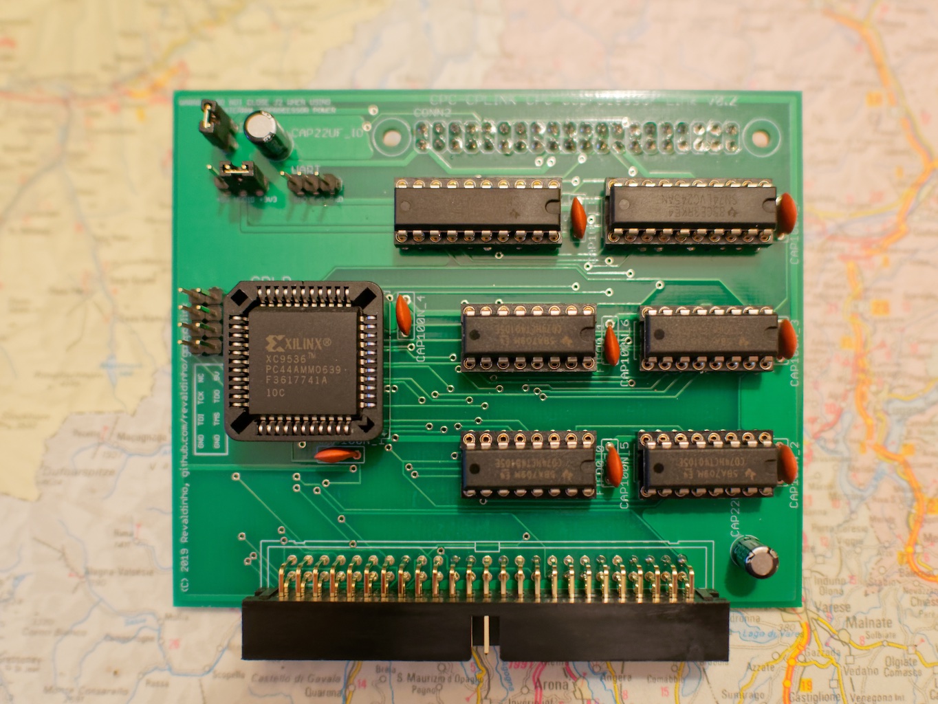
A first version of the card has been built and tested successfully. The prototype uses a small (but sadly now obsolete) Xilinx XC9536-PC44 CPLD to implement all logic other than level shifters and the FIFOs.
A second version of the card has been designed which uses only standard, through hole mounted, 74 Series ICs. New PCBs for this card should be available in early November. All behaviour should be identical between the two cards, so the prototypes are still good for all software development while waiting for the final version.
Full details of the connector pin assignments and GPIO assignments on RaspberryPi are provided later in the Hardware section. The coprocessor needs to have 13 pins available, connected as follows
| Signal Name | Direction (Relative to Copro.) | #Pins | Idle State | Comment |
|---|---|---|---|---|
| DATA | Bidirectional | 8 | Hi-Z | Data in and out of the FIFO card |
| DIR | Input | 1 | NA | Data Input Ready from FIFO card |
| DOR | Input | 1 | NA | Data Output Ready from FIFO card |
| SI | Output | 1 | 0 | Shift Data In to FIFO card (active low to high edge) |
| SOB | Output | 1 | 0 | Not Shift Data Out to FIFO card (active high to low edge) |
| WriteNotRead | Output | 1 | 0 | Signal Write (1) or Read (0) to FIFO Card |
When the interface is inactive the co-processor should drive or tristate the pins to the idle states as shown in the table above. This puts the FIFO in 'read mode' and the bidirectional data pins will be driven by the FIFO without any electrical conflict.
When data is available to the copro, the DOR signal will go high.
To read the data the copro runs through the following sequence
- Read data on the DATA inputs
- Pulse the SOB signal high then low
When the FIFO has space for data from the copro, the DIR signal will go high.
To write data to the FIFO the copro runs through the following sequence
- Drive the WriteNotRead signal high
- Drive the byte to be written onto the DATA lines
- Pulse the SI signal high then low
Take care that the SOB or SI pulse does not violate the minimum pulse width specification in the 75HCT40105 Datasheet. In the C example (see the sw/rpi_c directory) I found that a 'delayMicroseconds(60)' is needed for the pulse width to get reliable operation at 5V.
The FIFOs appear to the CPC as IO mapped locations at &FD81 and & FD80.
- IO Address &FD80 is the FIFO data register
- IO Address &FD81 is the FIFO status register
NB. To simplify address decoding and reduce the chip count on the 74 Series implementation of the FIFO board, the board actually requires 8 locations in IO space from &FD80 to &FD87. In this way, the FIFO registers appear mapped to every pair of even/odd addresses in this space.
Bits in the status register are assigned as follows
| bit | Name | Function |
|---|---|---|
| 2-7 | Unused | always return 'x' on reading |
| 1 | DIR | Data Input ready |
| 0 | DOR | Data Output Ready |
The DOR and DIR bits are read-only. When reading the status register the upper 6 bits must always be masked off since they are not driven by the FIFO card.
Writing any value to the status register will reset the FIFOs, and this should be done on starting up the interface.
Unlike the Co-processor side of the interface the FIFO IC Shift In (SI) and Not Shift Out (SOB) signals are not brought to the host side. These are generated on the fly by the board logic because a 4MHz Z80 IO cycle (which always includes an automatic wait state) is guaranteed to always meet the required pulse widths.
The read and write process for the host is much simpler than for the coprocessor.
When data is available to the host, the DOR bit in the status register will go high. So to read from the FIFO the host just needs to poll the FIFO status register and if the DOR bit is set to '1' then read from the FIFO Data IO register.
When the FIFO has space to write new data from the host, the DIR bit in the status register will go high. So again the procedure is just to poll the FIFO status register and if the DIR bit is set to '1' then write to the FIFO Data IO register.
This is a short and rather pedestrian demonstration of the FIFO in use between the CPC using BASIC, and a RaspberryPi (RPi) running Python in a full Raspbian (Linux) distribution.
The Python code for the RPi uses the standard GPIO.RPi library to control the GPIO pins. The code demonstrates how to check flags and read/write bytes to the FIFO as the RPi loops endlessly, listening for incoming data on one FIFO and echoing it back out through the other.
import RPi.GPIO as gpio
from collections import deque

#define BCM Pin Allocations
PIN_DATA = [11,10,9,8,7,4,3,2] # Data[7:0]
PIN_DIR = 17
PIN_SI = 18
PIN_SOB = 22
PIN_DOR = 23
PIN_WNR = 24

def setup_pins():
    gpio.setmode(gpio.BCM)
    gpio.setup(PIN_DATA,gpio.IN)
    gpio.setup(PIN_DIR, gpio.IN)
    gpio.setup(PIN_DOR, gpio.IN)
    gpio.setup(PIN_SI, gpio.OUT, initial=gpio.LOW)
    gpio.setup(PIN_SOB, gpio.OUT, initial=gpio.LOW)
    gpio.setup(PIN_WNR, gpio.OUT, initial=gpio.LOW)

def write_fifo_byte(txdata):
    gpio.output(PIN_WNR,gpio.HIGH)
    for (b,d) in zip(PIN_DATA,txdata):
        gpio.setup(b, gpio.OUT, initial=d)
    gpio.output(PIN_SI, gpio.HIGH)
    gpio.output(PIN_SI, gpio.LOW)
    for b in PIN_DATA:
        gpio.setup(b, gpio.IN)
    gpio.output(PIN_WNR, gpio.LOW)

def read_fifo_byte():
    rcv = [gpio.input(b) for b in PIN_DATA]
    gpio.output(PIN_SOB, gpio.HIGH)
    gpio.output(PIN_SOB, gpio.LOW)
    return(rcv)

if __name__ == "__main__":
    setup_pins()
    write_queue = deque(maxlen=8192)
    while True:
        if gpio.input(PIN_DOR):
            write_queue.append(read_fifo_byte())
        if len(write_queue)>0 and gpio.input(PIN_DIR):
            write_fifo_byte(write_queue.popleft())
The BASIC code for the CPC creates an array of 1024 random bytes, transmits the bytes to the RPi and receives them back from the RPi before checking that received data matches transmission and reporting data rates and any errors
10 DEFINT a-z
20 MODE 2
30 DIM tx[1024]: 'transmit data buffer
40 DIM rx[1024]: 'receive data buffer
50 OUT &FD81,0
60 PRINT "Setting up random data"
70 FOR i=0 TO 1023:tx[i]=INT(RND*256):NEXT i
80 i=0: 'tx byte count
90 j=0: 'rx byte count
100 PRINT "Sending/Receiving Data"
110 s!=TIME
120 WHILE i+j<>2048
130   IF i<>1024 AND (INP(&FD81) AND 2) THEN OUT &FD80,tx[i] :i=i+1
140   IF j<>1024 AND (INP(&FD81) AND 1) THEN rx[j]=INP(&FD80):j=j+1
150 WEND
160 dur!=(TIME-s!)/300:'timer in 300ths of sec
170 PRINT "Bytes sent: ";i
171 PRINT "Bytes Received: ";j
172 PRINT "Time: ";dur!;" s "
173 PRINT "Data rate: ";(1024*2)/dur!;" Bytes/s"
180 PRINT "Checking Data ...";
190 e=0
200 FOR i=0 TO 1024:IF rx[i]<>tx[i] THEN e=e+1: PRINT rx[i],tx[i]: NEXT
210 IF e=0 THEN PRINT "No errors" ELSE PRINT e;" errors detected"
220 END
To run the demo, save the python script as loopback.py on the RPi and the BASIC code as fifo.bas on the CPC (both are included in the sw/ directory). Then startup the RPi script first:
python loopback.py
Now start the CPC running:
RUN "FIFO.BAS
and you should see something like this
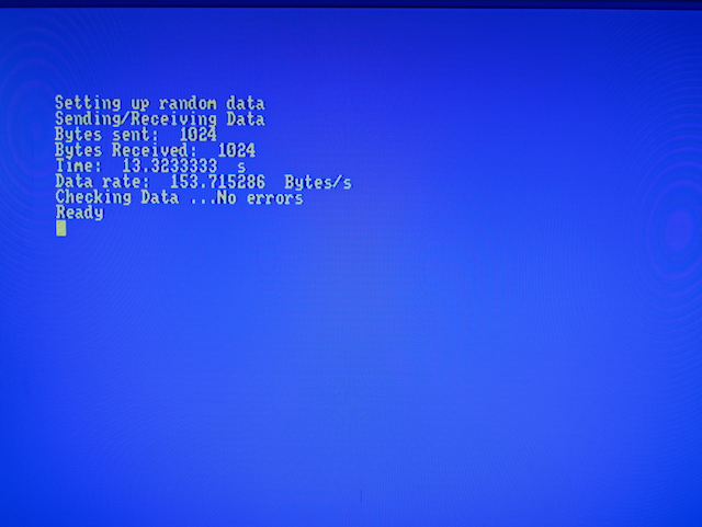
Theoretically the data rate that the CPC can support is around 50KBytes/s (if checking the status flag for each byte), but you will see numbers much lower than this with this demo. The main limitation here is the CPC BASIC loop: even without checking flags the loop takes around 13s to execute. Enabling the Pi adds nothing measurable to that and RPi.GPIO is known as one of the slower libraries executing in an interpreted language here.
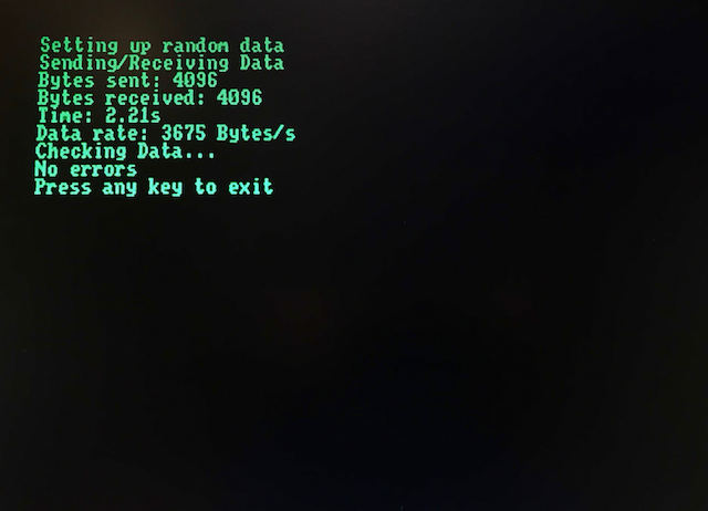
So, some faster CPC code is called for to do a better job and as a first stab at this there is a BCPL version of the CPC FIFO code in the sw/cpc_bcpl directory. This one is intended for compiling with Arnor's CPC BCPL and is already orders of magnitude faster than the BASIC. Here's the screenshot from the BCPL run with the Raspberry Pi still executing the same Python code, showing a 3675 Bytes/s transfer rate:
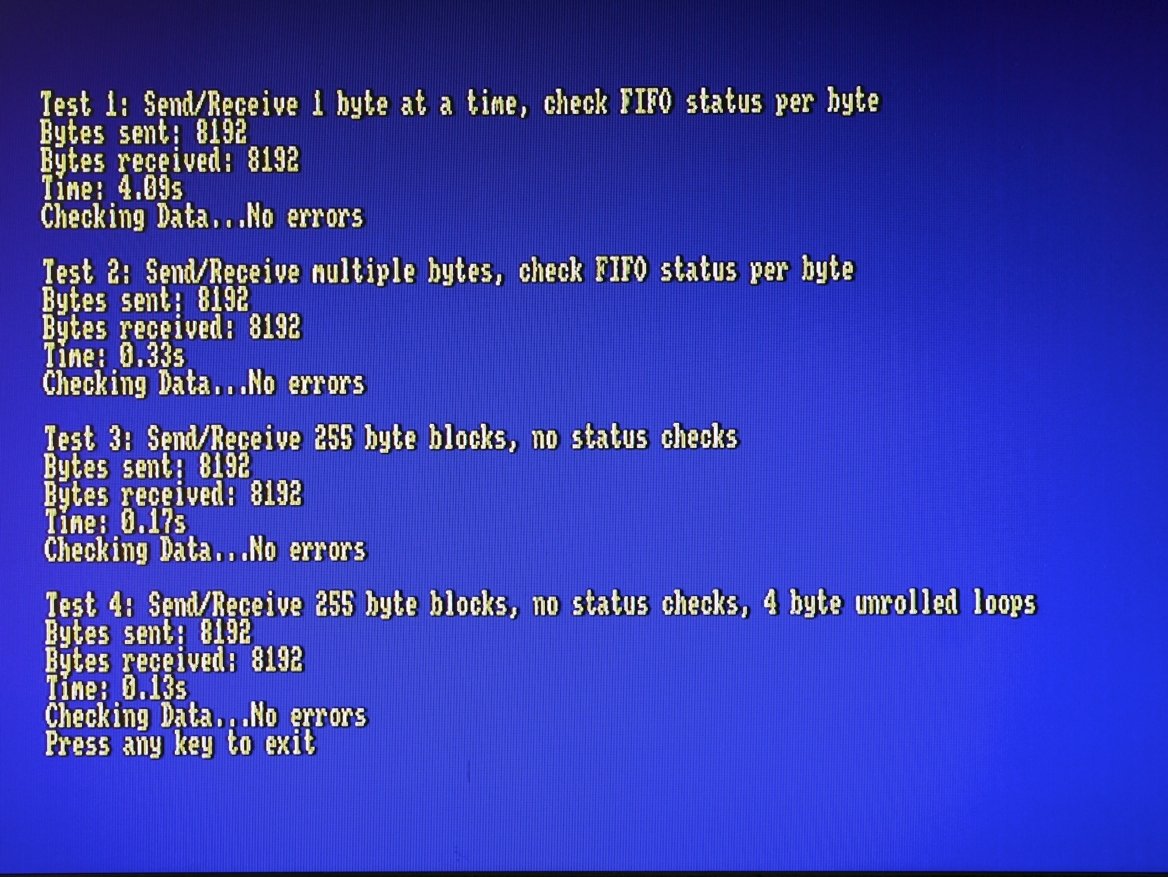
An improved BCPL Example makes better use of the buffer by reading and writing until the buffer is empty or full respectively. This boosts the throughput to about 6KBytes/s. At this point it's the interpreted Python on the Raspberry Pi which is the bottleneck, so finally an example in C is provided, again using the WiringPi library, and now with this running on the Pi a data rate of over 45KBytes/s can be obtained. In fact the Pi Zero is able to keep up with the CPC, so moving to a block transfer mode where only the Pi checks the FIFO flags can double this data rate, as shown in the screenshot below.
Below is a table showing data rates from combining the various example loopback programs for CPC and RaspberryPi Zero:
| Host | Co-Processor | Bytes | Run Time | Data rate | |||||
| Machine | Language | Code | Machine | OS | Language | GPIO Lib | Transferred | (s) | Bytes/s |
| CPC464 | Locomotive BASIC 1.2 | fifo.bas | Pi Zero | NA | NA | NA | 2048 | 13.33 | 153.6 |
| CPC464 | Locomotive BASIC 1.2 | fifo.bas | Pi Zero | Raspbian | Python | RPi.GPIO | 2048 | 13.33 | 153.6 |
| CPC464 | Locomotive BASIC 1.2 | fifo.bas | Pi Zero | Raspbian | Python | WiringPi | 2048 | 13.33 | 153.6 |
| CPC6128 | Locomotive BASIC 1.2 | fifo.bas | Pi Zero | Raspbian | C | WiringPi | 2048 | 13.33 | 153.6 |
| CPC464 | Arnor BCPL | fifo.b | Pi Zero | Raspbian | Python | RPi.GPIO | 8192 | 2.2 | 3723.6 |
| CPC464 | Arnor BCPL | fifo.b | Pi Zero | Raspbian | Python | WiringPi | 8192 | 2.2 | 3723.6 |
| CPC6128 | Arnor BCPL | fifo.b | Pi Zero | Raspbian | C | WiringPi | 8192 | 2.2 | 3723.6 |
| CPC6128 | Arnor BCPL | fifo2.b | Pi Zero | Raspbian | Python | RPi.GPIO | 16384 | 2.98 | 5498 |
| CPC6128 | Arnor BCPL | fifo2.b | Pi Zero | Raspbian | Python | WiringPi | 16384 | 2.74 | 5979 |
| CPC6128 | Arnor BCPL | fifo2.b (byte mode) | Pi Zero | Raspbian | C | WiringPi | 7000 | 0.30 | 46666 |
| CPC6128 | Arnor BCPL | fifo2.b (burst mode) | Pi Zero | Raspbian | C | WiringPi | 7000 | 0.16 | 87500 |
| CPC6128 | Arnor BCPL | fifo2.b (burst mode, unrolled loops) | Pi Zero | Raspbian | C | WiringPi | 7000 | 0.12 | 116666 |
A 40W connector is provided for the coprocessor and is configured so that a Raspberry pi can be plugged in directly on the back of the board. Other devices, e.g. Arduino, will need an adapter cable.
The pin-out of the connector and RaspberryPi GPIO connections are shown below.
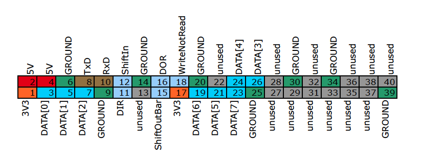
| Pin | Pi Pin name | Function |
|---|---|---|
| 1 | 3V3 | 3V3 Power into FIFO Board |
| 2 | 5V | 5V Power from FIFO Board |
| 3 | GPIO2 (SDA1) | FIFO DATA [0] |
| 4 | 5V | 5V Power from FIFO Board |
| 5 | GPIO3 (SCL1) | FIFO DATA [1] |
| 6 | GROUND | GROUND |
| 7 | GPIO4 | FIFO DATA [2] |
| 8 | GPIO14 (TxD) | UART TxD |
| 9 | GROUND | GROUND |
| 10 | GPIO15 (RxD) | UART RxD |
| 11 | GPIO17 | FIFO DATA INPUT READY (DIR) |
| 12 | GPIO18 | FIFO SHIFT IN (SI) |
| 13 | GPIO27 | unused |
| 14 | GROUND | GROUND |
| 15 | GPIO22 | NOT FIFO SHIFT OUT (SOB) |
| 16 | GPIO23 | FIFO DATA OUTPUT READY (DOR) |
| 17 | 3V3 | 3V3 Power into FIFO board |
| 18 | GPIO24 | FIFO WRITE NOT READ |
| 19 | GPIO10 (MOSI) | FIFO DATA[6] |
| 20 | GROUND | GROUND |
| 21 | GPIO09 (MISO) | FIFO DATA[5] |
| 22 | GPIO25 | unused |
| 23 | GPIO11 (SCLK) | FIFO DATA[7] |
| 24 | GPIO08 (CE0) | FIFO DATA[4] |
| 25 | GROUND | GROUND |
| 26 | GPIO07 (CE1) | FIFO DATA [3] |
| 27 | SDA0 (EEPROM) | unused |
| 28 | SCL0 (EEPROM) | unused |
| 29 | GPIO05 | unused |
| 30 | GROUND | GROUND |
| 31 | GPIO06 | unused |
| 32 | GPIO12 | unused |
| 33 | GPIO13 | unused |
| 34 | GROUND | GROUND |
| 35 | GPIO19 | unused |
| 36 | GPIO16 | unused |
| 37 | GPIO26 | unused |
| 38 | GPIO20 | unused |
| 39 | GROUND | GROUND |
| 40 | GPIO21 | unused |
Note that only the pins of the original RaspberryPi's 26W connector are used, so that the card is directly plug compatible with all Pis and with the IO board fitted in the Fuze T2 keyboard for both RPi1 and RPi2 revisions. However some GPIOs were renumbered after the very first Rev1 version of the RPi 1. The pin-out here applies to all current RaspberryPi models. For GPIO changes to use a Rev1 pi refer to SwiftyGPIO.
When using a RaspberryPi the Pi's UART RxD and Txd Signals are both brought out to pins on a three pin header so that a serial debugger can be easily connected. Arduinos offer similar features so when adapting one of those into the 40 way socket these pins should connect to the appropriate Arduino IOs.
The board has two jumpers affecting power to the co-processor header and the operating voltage on the interface:
- Jumper J1 : VDDIO jumper
- Jumper J2 : Copro +5V power
J1 is a 3 way header to select either 3V3 or 5V power for the two level shifter ICs. The 3V3 supply, if selected, is taken from the relevant pin on the 40W connector and must be supplied by the external card (usually a RaspberryPi). The 5V supply is always taken from the host power supply.
J2 is a simple 2 way header which will provide host +5V power from to the 40W connector when closed. This is intended mainly so that a small RaspberryPi Zero, or other low current variant, can be plugged into and powered from the FIFO card. For all other uses this jumper should be left open and external power provided to the coprocessor separately. For example, you must not close this jumper when using an RaspberryPi which is also being powered by its own USB input - that would short the two power supplies for which neither card has protection.
Depending on the FIFO board supply from the CPC it may be possible to power other models from the FIFO card, but recommended settings with RaspberryPis are
| Pi Model | J1 | J2 | Pi Power |
|---|---|---|---|
| A, A+, B+, 3A+, Zero, W | 3V3 | Closed | FIFO board supply |
| All other models | 3V3 | Open | External USB supply |
WARNING do not close J2 when any coprocessor is attached to the 40W connector and powered by an external (e.g. USB) supply.
More notes on board construction are provided on the following pages:
All programs and data files in this project are made available under the terms of the GNU General Public License v3.