[Bug] PCB Exposure - Gerber import is "clipped" on the Vertical Axis #1022
Description
System
UVtools v5.1.0 X64
Operative system: Microsoft Windows 10.0.22631 X64
Processor: 12th Gen Intel(R) Core(TM) i5-12600K
Processor cores: 16
Memory RAM: 14.30 / 31.79 GB
Runtime: win-x64
Framework: .NET 9.0.4
AvaloniaUI: 11.3.0
OpenCV: 4.10.0

Sreens, resolution, working area, usable area:
1: 2560 x 1440 @ 100% (Primary) (On this)
    WA: 2560 x 1400    UA: 2560 x 1400
2: 1920 x 1080 @ 100%
    WA: 1920 x 1040    UA: 1920 x 1040
3: 1920 x 1080 @ 100%
    WA: 1920 x 1040    UA: 1920 x 1040

Path:       C:\Program Files\UVtools\
Executable: C:\Program Files\UVtools\UVtools.exe
Loaded file: PCB.goo [Version: 0] [Class: GooFile]
Printer and Slicer
- Printer: Elegoo Saturn 4 Ultra
- Slicer: Chitubox (Used to create a "dummy" .goo file.
Description of the bug
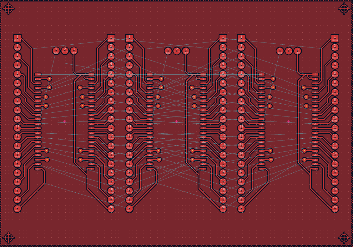
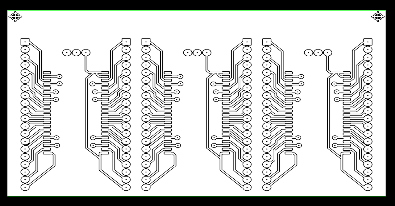
When importing a Gerber file generated using KiCad 9, the gerber's vertical axis is clipped when importing using "Tools > PCB Exposure". This causes some of the PCB Artwork/geometry to be missing.
How to reproduce
Repro Steps:
For reference, the KiCad 9 project used for this can be found here
Settings for the gerber export/plot were as follows
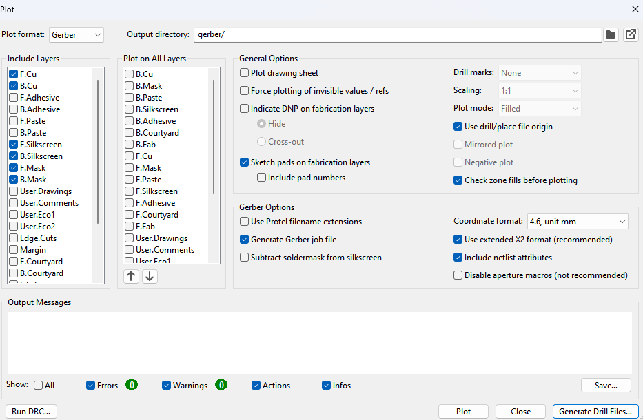
- Download gerber.zip.
- Extract the two Gerber files, "BIOS Adapter-F_Cu.gbr" and "BIOS Adapter-PTH.drl" from gerber.zip.
- Use Chitubox to generate a dummy sliced file and save as *.goo format. For convenience, feel free to use PCB.zip.
- Open UVTools and open the extracted PCB.goo file (File > Open > PCB.goo).
- Navigate to Tools > PCB Exposure.
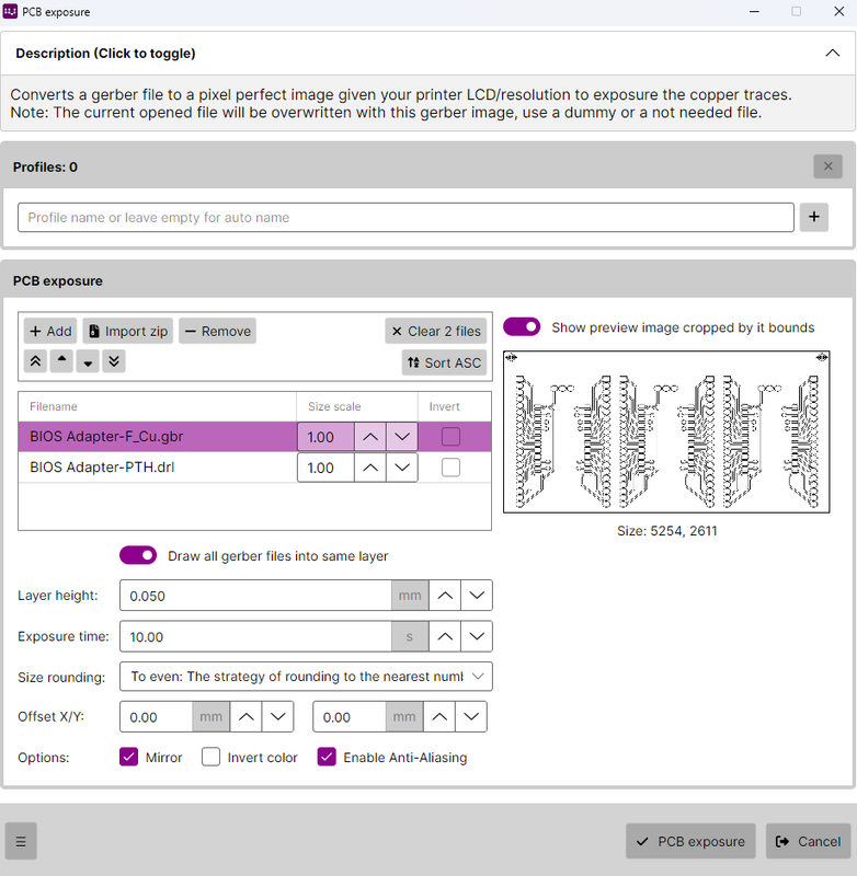
- Under the PCB exposure section in the dialog popup, select "Add" and select both "BIOS Adapter-F_Cu.gbr" and "BIOS Adapter-PTH.drl".
- Select "BIOS Adapter-F_Cu.gbr" from the file preview list under the "PCB exposure pane" within the currently open dialog.
- Notice that the preview pane displays the Gerber file with a chunk of the vertical axis clipped/missing.
- Select "Create one layer per gerber file".
- Click the "PCB exposure" button at the bottom of the dialog.
- Notice that the imported Gerber image layer is missing some of the vertical axis.
Anyway, just as an aside, I really love this feature of UVTools and am glad it exists, you did an excellent job with it.
Files
No response
Metadata
Metadata
Assignees
Labels
No labels