How to Build a Custom NeoPixel Matrix
But 1000 5mm NeoPixels from AliExpress (click here)
Using the template (click here), design your faceplate and cut it on a CNC machine. Note that you'll need to clone this repository, then navigate to the "~/readme/Custom NeoPixel Matrix" folder. From there you can open the "faceplate template.dxf" in your favorite CAD editor.
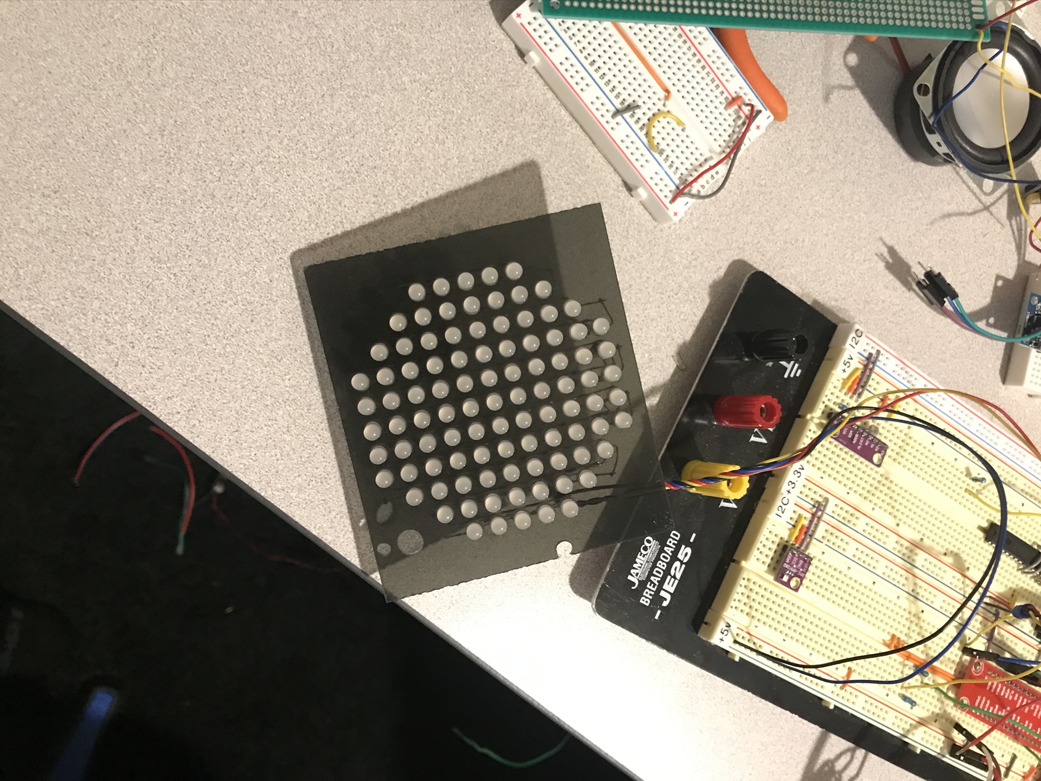
Install the NeoPixels. Through trial and error, I came up with a system that works pretty well, You can put in 10 pixels in about 20 minutes, once you get past the learning curve. These pics should help get you started:
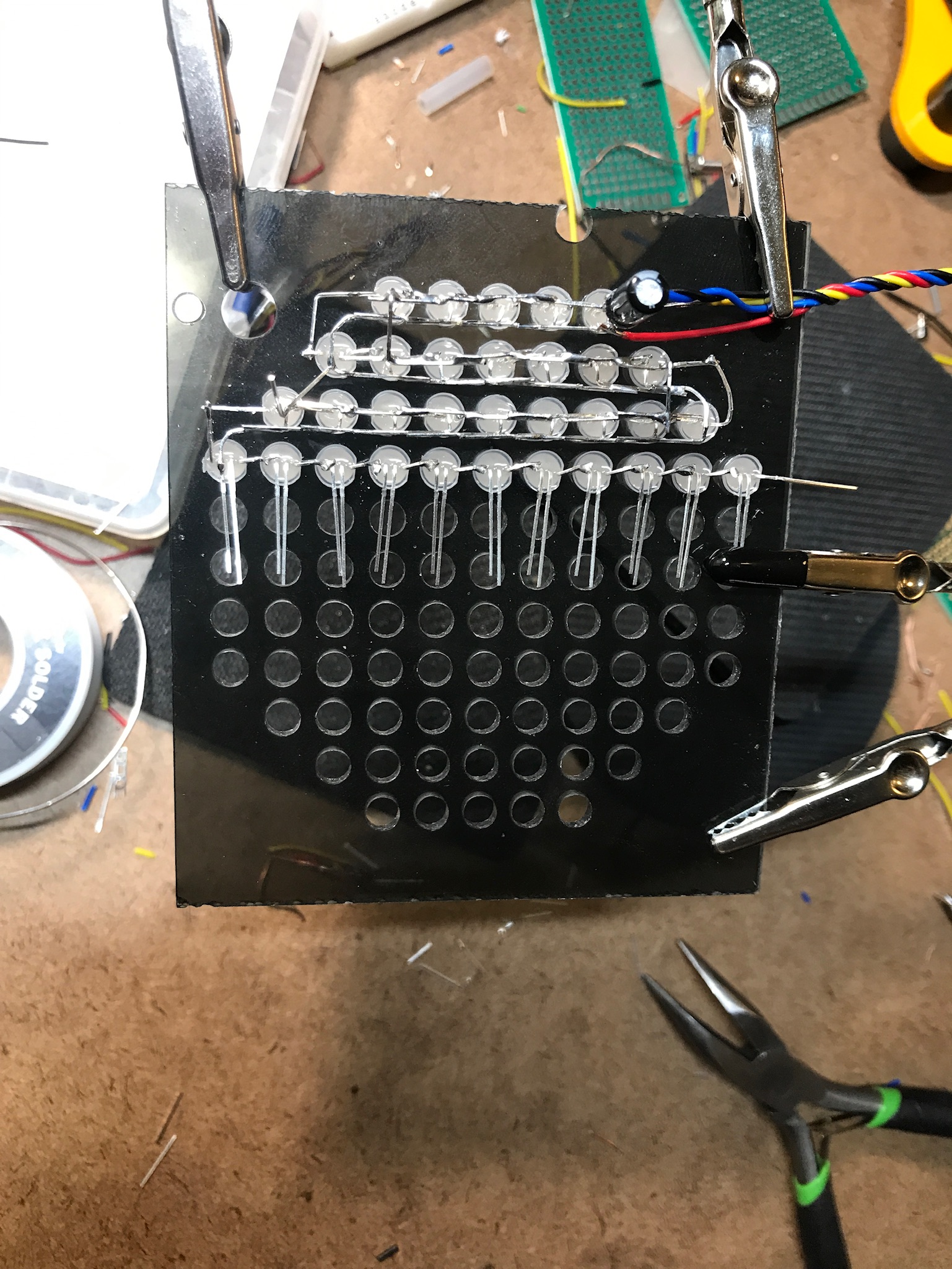
I found that installing the LED's one row at a time, worked pretty well. I also stopped and tested each row to make sure I hadn't made a mistake. Invariably I would forget to connect either the +voltage or ground circuit. Note that every other row is opposite. The pixels I bought had two short leads and two long leads. In the first photo, I have the short leads on the left, so the previous and next row will have the short leads on the right. I installed a 22 mfd capacitor ever 50 pixels or so, but no resistors, so I can't run them at full brightness (255) or else they will over heat and burn out.
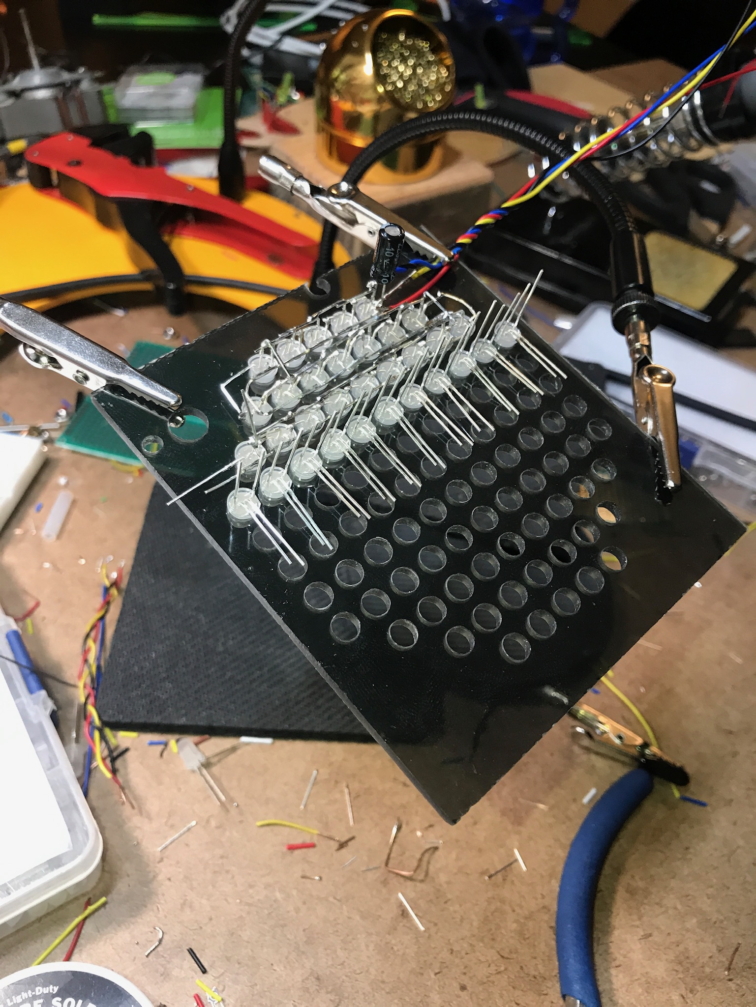
Also, I would start out pulling the middle two leads down, as shown in the first and second photo, which are the same, just from different angles.
Photo 1
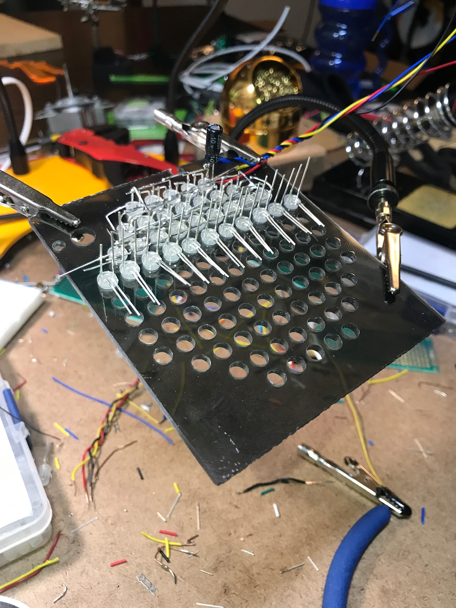
Photo 2
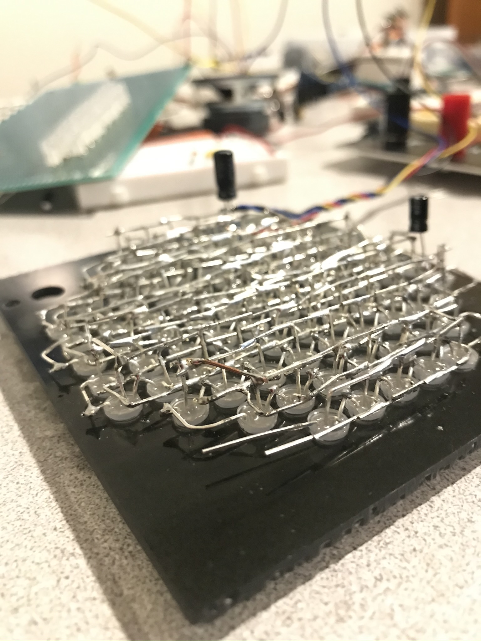
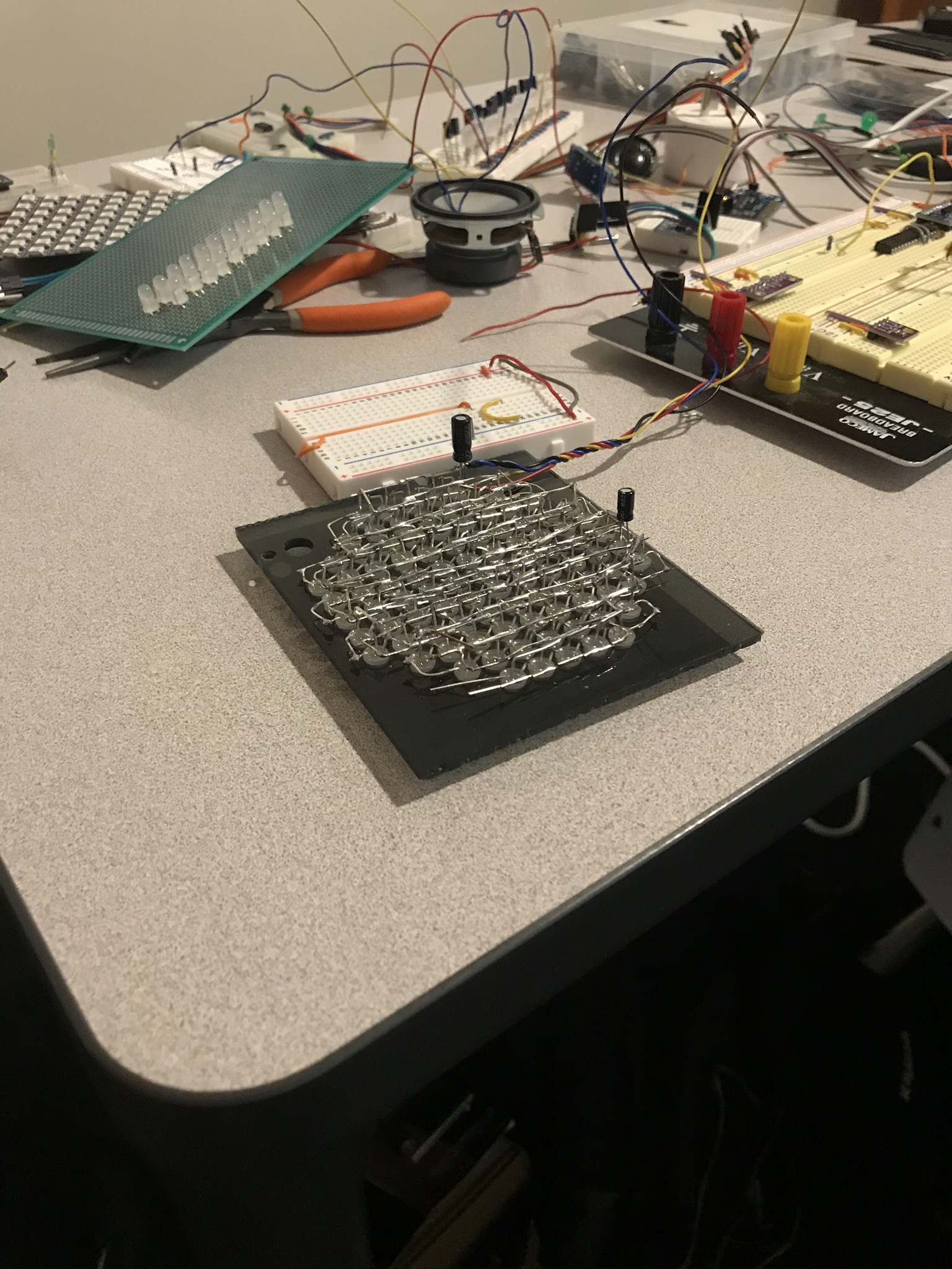
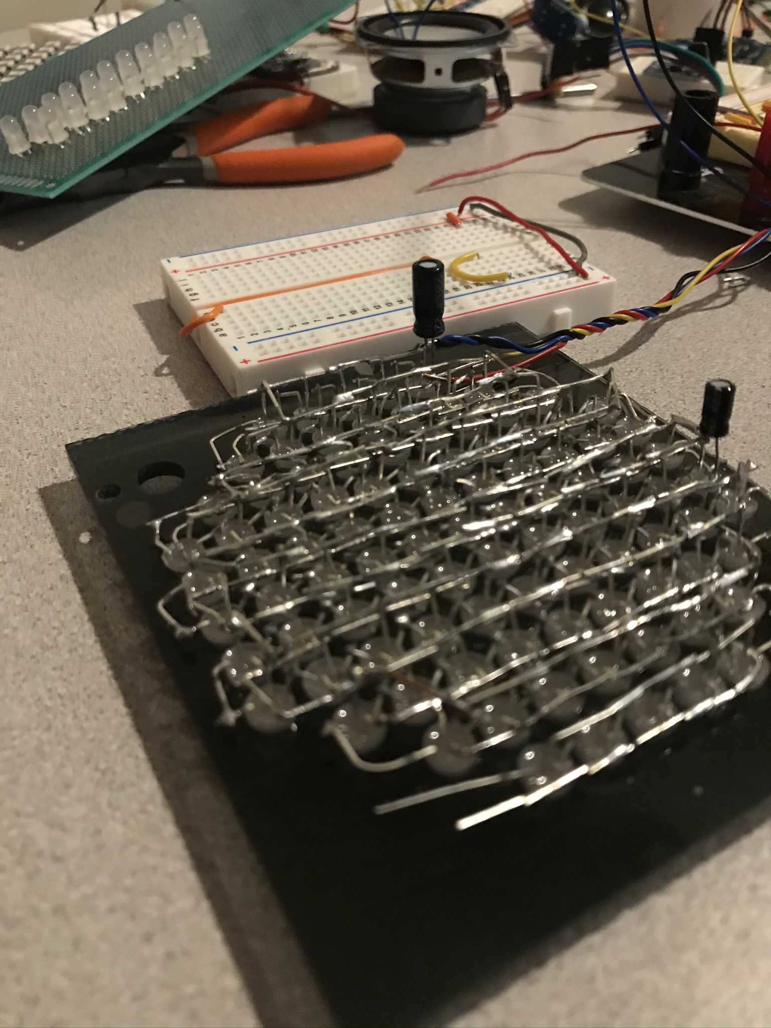
In this third and fourth, and fifth photos you can see that I was crossing the data out lead from the left LED with the data in lead from the right LED, then touching the crossing point with a bit of solder, then cutting of the excess leads. This was the most time consuming part as I had to do them one at a time, or else the leads would get in the way of each other. Also, I found that pulling the leads back to a 45 degree angle really helped keep me straight and helped with keeping the leads of of the way of the ground leads in the next step.
photo 3
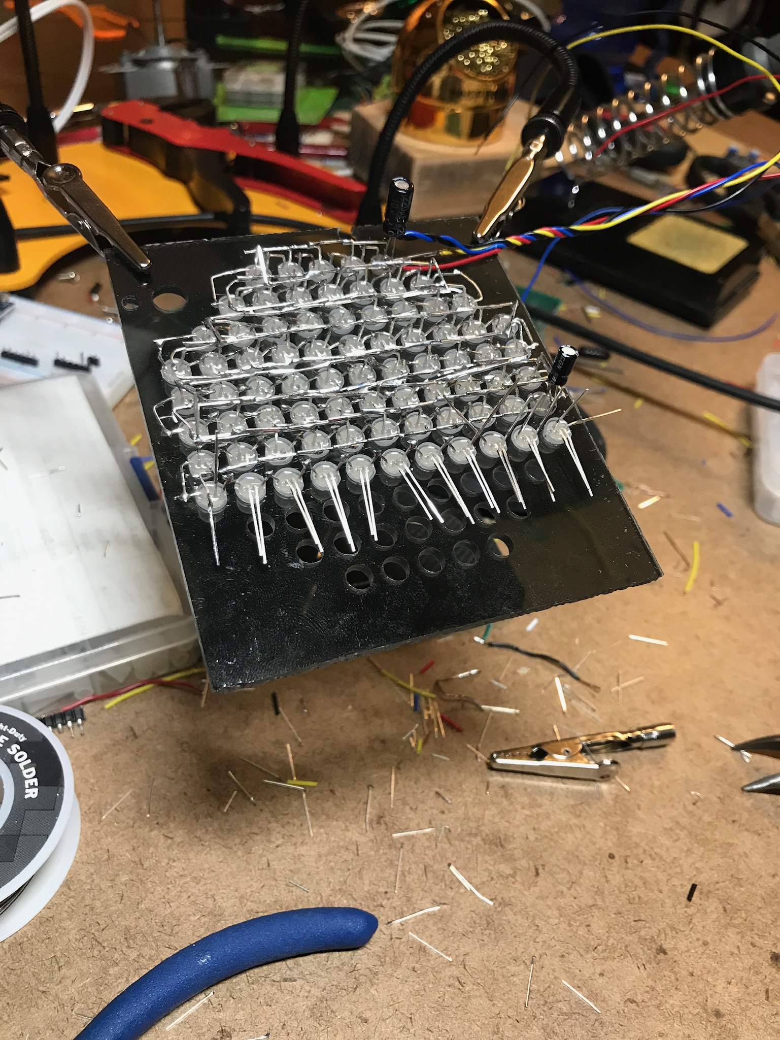
photo 4
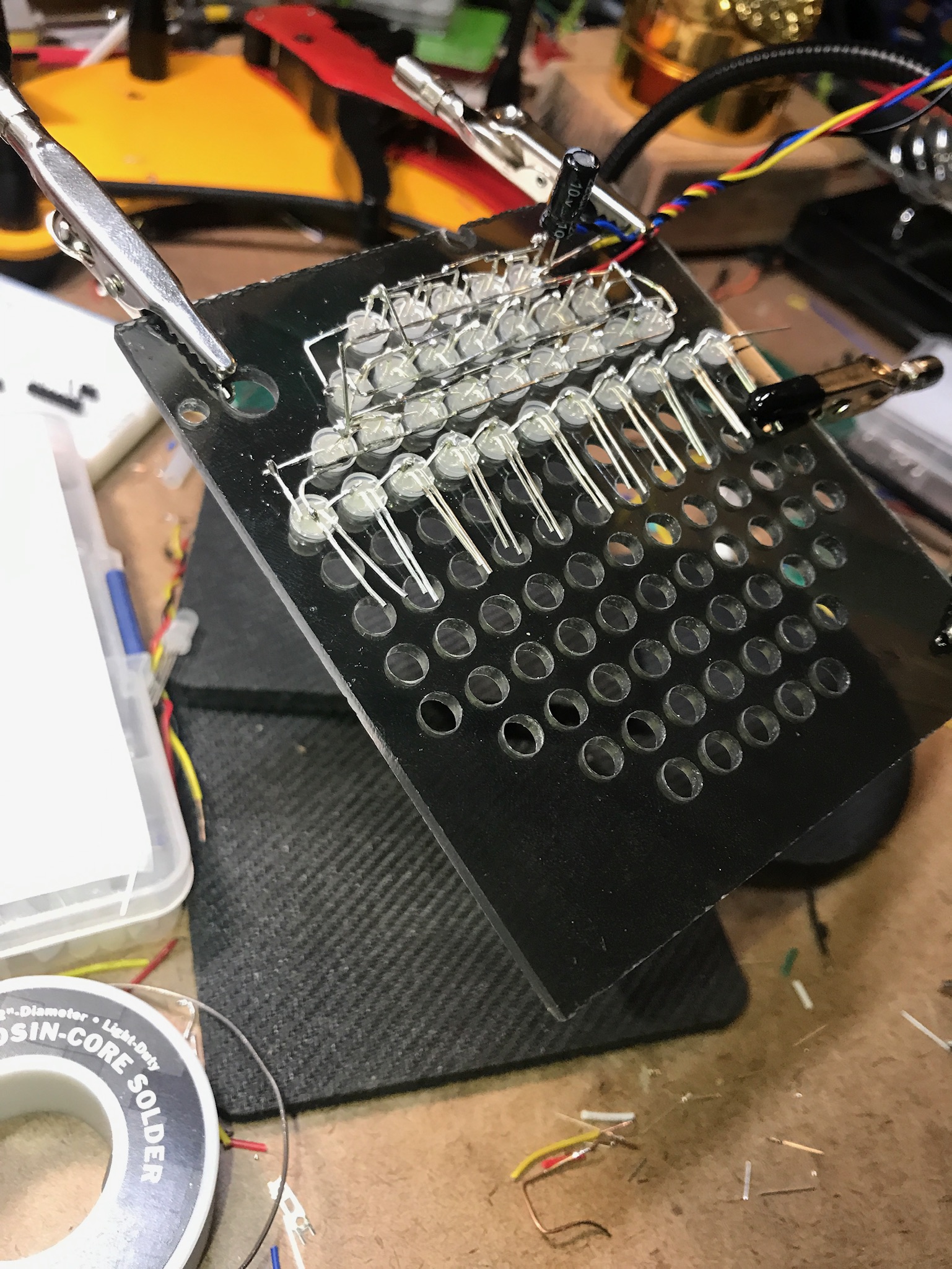
photo 5
In the sixth photo, you can see the top bridge I made using the ground leds, bending each one in an L shape across the top to meet the next ground lead in the row.
photo 6
60
70
80
85
Short video demo: build-90