This project demonstrates how to build a Digital Audio Volume Control Circuit using the PT2258 IC and Arduino, offering superior performance compared to traditional analog potentiometers. The PT2258 provides precise digital volume control with an attenuation range of 0-79dB in accurate 1dB steps, making it ideal for audio amplifiers, home theater systems, and professional audio applications.
Original Project Link: Digital Audio Volume Control Circuit using PT2258 IC and Arduino
- Features
- Why Digital Volume Control?
- PT2258 IC Specifications
- Components Required
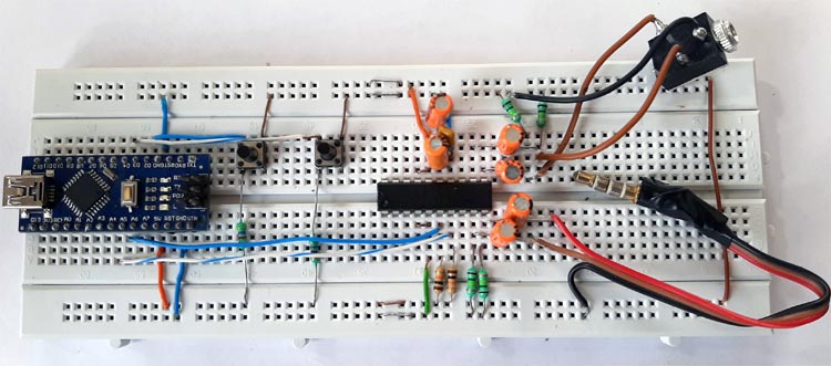
- Circuit Diagram
- Pin Configuration
- Hardware Setup
- Software Requirements
- Installation & Setup
- Code Explanation
- How It Works
- Testing the Circuit
- Applications
- Troubleshooting
- Future Enhancements
- FAQ
- License
- Contributing
✅ 6-Channel Digital Volume Control - Perfect for stereo and 5.1 surround sound systems
✅ Precise 1dB Step Control - 80 discrete volume levels (0dB to -79dB)
✅ I2C Interface - Easy integration with Arduino, Raspberry Pi, and other microcontrollers
✅ No Mechanical Wear - Virtually unlimited lifespan compared to potentiometers
✅ High Signal-to-Noise Ratio - >100dB for crystal-clear audio
✅ Excellent Channel Separation - >90dB at 1KHz
✅ Remote Control Capability - Control volume via buttons, rotary encoders, or wireless modules
✅ Low Distortion - THD <0.01% at 1KHz
| Feature | Digital Volume Control (PT2258) | Mechanical Potentiometer |
|---|---|---|
| Precision | 1dB step accuracy, digital repeatability | Variable, depends on physical position |
| Channel Separation | >90dB | Poor matching between channels |
| Signal-to-Noise Ratio | >100dB | 60-80dB typical |
| Lifespan | No mechanical wear, virtually unlimited | Limited (10,000-50,000 cycles) |
| Remote Control | Easy I2C integration | Requires motorized solution |
| Noise | Low noise, no scratching | Contact noise, crackling over time |
The PT2258 is a 6-channel electronic volume controller IC built with CMOS technology for multi-channel audio-video applications.
- Control Interface: I2C bus (SCL and SDA lines) with max clock frequency of 100KHz
- Attenuation Range: 0dB to -79dB in accurate 1dB steps (80 discrete levels)
- Channels: 6 independent input/output channels
- Channel Separation: >90dB at 1KHz
- Signal-to-Noise Ratio: >100dB
- Operating Voltage: 5V to 9V DC
- I2C Addressing: 4 selectable addresses (0x80, 0x84, 0x88, 0x8C)
- Package: 20-pin DIP or SOP
- THD: <0.01% at 1KHz
- Input Impedance: 27KΩ typical
| CODE1 (Pin 17) | CODE2 (Pin 4) | HEX Address |
|---|---|---|
| 0 (GND) | 0 (GND) | 0x80 |
| 0 (GND) | 1 (VCC) | 0x84 |
| 1 (VCC) | 0 (GND) | 0x88 |
| 1 (VCC) | 1 (VCC) | 0x8C |
| Component | Quantity | Specification |
|---|---|---|
| PT2258 IC | 1 | 20-pin DIP package |
| Arduino Nano | 1 | Or any compatible Arduino board |
| Push Buttons | 2 | Tactile push buttons |
| 4.7kΩ Resistor (5%) | 2 | For I2C pull-up |
| 150kΩ Resistor (5%) | 4 | Input/output coupling |
| 10kΩ Resistor (5%) | 2 | Button pull-down |
| 10µF Capacitor | 6 | Electrolytic, 16V+ |
| 0.1µF Capacitor | 1 | Ceramic, power decoupling |
| Breadboard | 1 | For prototyping |
| Screw Terminal (5mm) | 3 | Audio input/output connections |
| Jumper Wires | 10+ | Male-to-male |
- Audio Amplifier (e.g., TDA2050, LM3886)
- Speakers (4Ω to 8Ω)
- Audio Source (phone, MP3 player, etc.)
- Power Supply (5V for Arduino, separate for amplifier)
PT2258 IC Connections:
- Pin 1 (GND): Ground
- Pin 2 (VCC): 5V power supply
- Pin 3-10: Audio input/output channels (FL, FR, CEN, SUB, RL, RR)
- Pin 11 (SDA): I2C data line (connect to Arduino A4)
- Pin 12 (SCL): I2C clock line (connect to Arduino A5)
- Pin 4 (CODE2): GND for address 0x80
- Pin 17 (CODE1): GND for address 0x80
Arduino Connections:
- A4 (SDA): Connect to PT2258 Pin 11 (via 4.7kΩ pull-up to 5V)
- A5 (SCL): Connect to PT2258 Pin 12 (via 4.7kΩ pull-up to 5V)
- D2: Volume Up button (with 10kΩ pull-down)
- D4: Volume Down button (with 10kΩ pull-down)
- GND: Common ground
- 5V: Power supply
| Software Channel | PT2258 Pin | Typical Application |
|---|---|---|
| Channel 0 | Pin 3 (FL) | Front Left (5.1 systems) |
| Channel 1 | Pin 5 (FR) | Front Right (5.1 systems) |
| Channel 2 | Pin 7 (CEN) | Center Channel |
| Channel 3 | Pin 8 (SUB) | Subwoofer |
| Channel 4 | Pin 9 (RL) | Rear Left / Stereo Left |
| Channel 5 | Pin 10 (RR) | Rear Right / Stereo Right |
-
Place the PT2258 IC on the breadboard
-
Connect power pins:
- Pin 1 (GND) to breadboard ground rail
- Pin 2 (VCC) to breadboard 5V rail
- Add 0.1µF capacitor between VCC and GND (close to IC)
-
Configure I2C address:
- Connect Pin 4 (CODE2) to GND
- Connect Pin 17 (CODE1) to GND
- This sets I2C address to 0x80
-
Setup I2C communication:
- Connect PT2258 Pin 11 (SDA) to Arduino A4
- Connect PT2258 Pin 12 (SCL) to Arduino A5
- Install 4.7kΩ pull-up resistors from SDA to 5V
- Install 4.7kΩ pull-up resistors from SCL to 5V
-
Connect buttons:
- Button 1 (Volume Up): One side to Arduino D2, other to 5V (with 10kΩ pull-down)
- Button 2 (Volume Down): One side to Arduino D4, other to 5V (with 10kΩ pull-down)
-
Audio connections:
- Connect audio input to desired PT2258 input channels (e.g., Pin 9 & 10 for stereo)
- Add 150kΩ resistors and 10µF capacitors for AC coupling
- Connect PT2258 output channels to amplifier input
-
Common ground:
- Ensure all grounds (Arduino, PT2258, audio source, amplifier) are connected together
- Wire Library (built-in) - For I2C communication
- PT2258 Library - Custom library for PT2258 control
- ezButton Library - For button debouncing and control
The PT2258 library requires a small fix for compatibility with modern Arduino IDE:
- Download the library from: PT2258 GitHub Repository
- Extract the ZIP file
- Open
PT2258.cppwith a text editor - Important Fix: Change
#include <wire.h>to#include <Wire.h>(capital W) - Save the file
- Copy the folder to
Arduino/libraries/
- Open Arduino IDE
- Go to Sketch → Include Library → Manage Libraries
- Search for "ezButton"
- Click Install
- Connect Arduino Nano to computer via USB
- Open Arduino IDE
- Select correct board: Tools → Board → Arduino Nano
- Select correct processor: Tools → Processor → ATmega328P (Old Bootloader) (if needed)
- Select correct port: Tools → Port → COM[X] (your Arduino's port)
- Copy the complete code (provided below)
- Click Upload button
- Open Serial Monitor (Ctrl+Shift+M) at 9600 baud
- Verify initialization message: "PT2258 Successfully Initiated"
#include
#include
#include

PT2258 pt2258;           // PT2258 Object
ezButton button_1(2);    // Volume Up Button on Pin 2
ezButton button_2(4);    // Volume Down Button on Pin 4

int volume = 40;         // Default starting volume (0-79, where 0=max, 79=min)

void setup() {
  Serial.begin(9600);           // Initialize serial communication
  Wire.setClock(100000);        // Set I2C clock to 100KHz (CRITICAL!)

  // Check PT2258 initialization
  if (!pt2258.init())
    Serial.println("PT2258 Successfully Initiated");
  else
    Serial.println("Failed to Initiate PT2258");

  // Configure button debounce delay
  button_1.setDebounceTime(50);
  button_2.setDebounceTime(50);

  // Set default volume for stereo channels (Channel 4 & 5)
  pt2258.setChannelVolume(volume, 4);  // Left channel
  pt2258.setChannelVolume(volume, 5);  // Right channel
}

void loop() {
  button_1.loop();  // Update button state
  button_2.loop();  // Update button state

  // Volume Up button pressed (increases attenuation = decreases volume)
  if (button_1.isPressed()) {
    volume++;
    if (volume >= 79)
      volume = 79;  // Maximum attenuation limit

    Serial.print("Volume: ");
    Serial.println(volume);

    pt2258.setChannelVolume(volume, 4);  // Update left channel
    pt2258.setChannelVolume(volume, 5);  // Update right channel
  }

  // Volume Down button pressed (decreases attenuation = increases volume)
  if (button_2.isPressed()) {
    volume--;
    if (volume <= 0)
      volume = 0;  // Minimum attenuation limit (maximum volume)

    Serial.print("Volume: ");
    Serial.println(volume);

    pt2258.setChannelVolume(volume, 4);  // Update left channel
    pt2258.setChannelVolume(volume, 5);  // Update right channel
  }
}Wire.setClock(100000); // MUST be 100KHz or lower!Critical: PT2258 maximum I2C clock is 100KHz. Higher speeds will cause communication failure.
- 0 = Maximum volume (0dB attenuation)
- 79 = Minimum volume (-79dB attenuation)
- Each step = 1dB change
pt2258.setChannelVolume(volume, channel);- Controls individual channel volume
- Channel 4 & 5 = Stereo left/right
- Can independently control all 6 channels
The PT2258 requires proper initialization:
- Wait 200ms after power-on
- Clear register with 0xC0 command
- Set initial volume values
All this is handled by pt2258.init() in the library.
The PT2258 communicates via I2C bus with the following sequence:
- Start Condition: SDA goes LOW while SCL is HIGH
- Address Byte: Send device address (0x80 for default config)
- Acknowledge: PT2258 pulls SDA LOW on 9th clock
- Data Byte: Send volume control command
- Acknowledge: PT2258 acknowledges data receipt
- Stop Condition: SDA goes HIGH while SCL is HIGH
Unlike analog potentiometers that create voltage dividers, the PT2258 uses:
- Digital-to-Analog Converters (DACs) for precise attenuation
- Resistor ladder networks for accurate 1dB steps
- Electronic switches (no mechanical parts)
- Low-noise signal path for >100dB SNR
Critical timing requirements:
- 200ms delay after power-on before first I2C command
- Register clear with 0xC0 command
- Sequential volume setting: Send 10dB steps followed by 1dB adjustments
- Maximum I2C speed: 100KHz
All these requirements are managed automatically by the PT2258 library.
Equipment needed:
- Powered speakers or audio amplifier
- Audio source (phone, MP3 player, computer)
- Multimeter (for voltage checks)
- Oscilloscope (optional, for signal analysis)
-
Power-on test:
- Connect 5V power to Arduino and circuit
- Check Serial Monitor for "PT2258 Successfully Initiated"
- Verify 5V on PT2258 Pin 2, 0V on Pin 1
-
I2C communication test:
- Use I2C scanner sketch to detect PT2258 at address 0x80
- Check for pull-up resistors on SDA/SCL lines (should read ~2.5V when idle)
-
Button test:
- Press Volume Up button - Serial Monitor should show increasing volume value
- Press Volume Down button - Serial Monitor should show decreasing volume value
-
Audio test:
- Connect audio source to PT2258 input
- Connect PT2258 output to amplifier
- Play audio and adjust volume with buttons
- Verify smooth, noise-free volume changes
✅ Precise 1dB step control
✅ No mechanical noise or scratching
✅ No channel imbalance
✅ Clean audio throughout volume range
✅ No audible "stepping" artifacts
This digital volume control circuit is ideal for:
- 🔊 Home Theater Systems - 5.1 and 7.1 surround sound control
- 🎵 Stereo Amplifiers - High-fidelity audio systems
- 🎤 PA Systems - Professional audio applications
- 📻 Multi-Zone Audio - Whole-home audio distribution
- 🎧 Headphone Amplifiers - Precise volume control
- 🎚️ Mixing Consoles - Channel level control
- 📺 TV Audio Systems - Enhanced audio control
- 🎮 Gaming Setups - Precise game audio adjustment
Possible causes:
- I2C wiring incorrect (SDA/SCL swapped)
- Missing or wrong value pull-up resistors
- Wrong I2C address configuration
- I2C clock speed too high
Solutions:
- Verify SDA to A4, SCL to A5
- Install 4.7kΩ pull-ups on both lines
- Check CODE1 and CODE2 pins are grounded for 0x80 address
- Ensure
Wire.setClock(100000);is in setup()
Possible causes:
- Wrong channel numbers in code
- Audio connections incorrect
- Volume variable out of range
Solutions:
- Verify channels 4 & 5 are used for stereo
- Check audio input/output wiring
- Monitor Serial output to verify volume changes
Possible causes:
- Long wires acting as antennas
- Poor ground connections
- Digital noise coupling
- Missing decoupling capacitors
Solutions:
- Keep all wires short (<6 inches)
- Use star ground configuration
- Add 0.1µF capacitor near PT2258 VCC pin
- Separate digital and analog grounds
- Consider moving to PCB design
Issue: I2C scanner shows 0x44 instead of 0x88
Explanation: Some I2C scanners use 7-bit addresses (shift right by 1 bit)
- 0x88 >> 1 = 0x44
- Both are correct, just different representation
Solution: Use 0x80, 0x84, 0x88, or 0x8C based on CODE1/CODE2 configuration
Possible causes:
- Loose breadboard connections
- Insufficient power supply
- Button bounce issues
Solutions:
- Firmly press all components into breadboard
- Use regulated 5V power supply with adequate current
- Increase debounce time:
button.setDebounceTime(100);
-
PCB Design
- Solid ground plane for reduced EMI
- Shorter traces for better high-frequency performance
- SMD components for compact design
- Shielded analog sections
-
Rotary Encoder Interface
- Replace buttons with rotary encoder
- Add OLED display for volume level
- Implement menu system for individual channel control
-
Remote Control
- Add IR receiver for infrared remote
- Implement Bluetooth control via smartphone app
- WiFi integration for smart home systems
-
Additional Features
- Mute function with relay or electronic switch
- Input selector switch for multiple sources
- Tone control integration (bass, treble)
- Balance control for left/right channels
-
Advanced Control Modes
- Logarithmic volume curve (more natural perception)
- Independent channel control via serial commands
- Preset volume levels (save/recall)
- Auto-volume limiting for hearing protection
-
Communication Protocols
- MQTT integration for IoT control
- Serial commands for external control
- Web interface via ESP8266/ESP32
- USB HID for computer volume control
-
User Interface
- OLED/LCD display showing volume level
- LED bar graph volume indicator
- Graphical channel level meters
- Channel configuration menu
Digital volume control uses integrated circuits (like PT2258) to electronically adjust audio levels via digital commands. It offers precise 1dB steps, no mechanical wear, excellent channel separation (>90dB), and remote control capability. Analog potentiometers mechanically create voltage dividers, suffer from contact noise, channel imbalance, limited lifespan (10,000-50,000 cycles), and cannot be controlled remotely.
The PT2258 offers excellent value with 6 independent channels (perfect for 5.1 surround), 100dB+ signal-to-noise ratio, simple I2C interface compatible with Arduino/Raspberry Pi, 0 to -79dB attenuation range in 1dB steps, and costs under $3. Comparable ICs like PGA2310 or CS3310 offer higher performance but cost 10-15 times more, making PT2258 ideal for DIY audio projects.
Yes, the PT2258 works with any audio amplifier accepting line-level inputs (typically 0.5-2V RMS). Compatible amplifiers include TDA2050, LM3886, TDA7293, Class D amplifiers, and tube amps with proper impedance matching. The PT2258 has 27kΩ input impedance and low output impedance, preventing signal loading or impedance mismatches.
The PT2258 supports a maximum I2C clock frequency of 100KHz. Higher frequencies may cause communication failures, missed acknowledgments, and erratic volume control. Arduino's default Wire library uses 100KHz, but some microcontrollers default to 400KHz (Fast Mode), requiring Wire.setClock(100000) to set proper speed. Slower speeds (10-50KHz) work reliably with minimal performance impact.
Yes, the PT2258 allows independent volume control of all 6 channels via software: pt2258.setChannelVolume(attenuation, channel). Channels 0-5 correspond to FL, FR, CEN, SUB, RL, RR pins. This enables custom volume profiles like boosted subwoofer bass, enhanced center channel dialogue clarity, or asymmetric stereo balance.
Noise sources and solutions include:
- Power supply noise: Add 100µF + 0.1µF capacitors at PT2258 VCC
- Digital noise coupling: Use separate ground planes or star grounding
- Long wires: Keep I/O wires under 6 inches or use shielded cable
- Breadboard parasitic capacitance: Transition to PCB with proper ground plane
Proper implementation can achieve the PT2258's specified >100dB SNR, reducing noise floor by 15-20dB.
Common causes include:
- Incorrect I2C wiring (SDA/SCL swapped or disconnected)
- Missing or wrong pull-up resistors (should be 4.7kΩ)
- Wrong I2C address (check CODE1/CODE2 pin configuration)
- I2C clock speed too high (must be ≤100KHz)
Verify connections, install proper pull-ups, confirm address settings, and ensure Wire.setClock(100000); is called in setup().
You can connect up to 4 PT2258 ICs on the same I2C bus using the 4 available addresses (0x80, 0x84, 0x88, 0x8C) by configuring CODE1 and CODE2 pins differently for each IC. This enables 24-channel control for complex multi-zone audio systems or professional audio applications.
This project is based on the tutorial from CircuitDigest.
The PT2258 library is available at: GitHub - sunrutcon/PT2258
This README is provided for educational purposes. Please respect original authors' work and licensing terms.
Contributions to improve this project are welcome! You can:
- Report bugs or issues
- Suggest new features or enhancements
- Submit pull requests with improvements
- Share your implementations and modifications
For detailed discussions or questions, visit the CircuitDigest Forum.
- Voice Controlled FM Radio using Arduino and Google Assistant
- Simple Audio Tone Control Circuit
- Gesture Controlled Media Player using Raspberry Pi and MediaPipe
- Arduino projects
- CircuitDigest Engineering Team - Original project creators
- sunrutcon - PT2258 Arduino library developer
- Princeton Technology Corp - PT2258 IC manufacturer
For questions and support:
- 📧 Visit CircuitDigest Support
- 💬 Join discussions at CircuitDigest Forum
- 📚 Check PT2258 Datasheet
Project Status: ✅ Tested and Working
Last Updated: November 2025
Difficulty Level: Intermediate
Estimated Build Time: 2-3 hours
Made with ❤️ by the Arduino and Audio Enthusiast Community