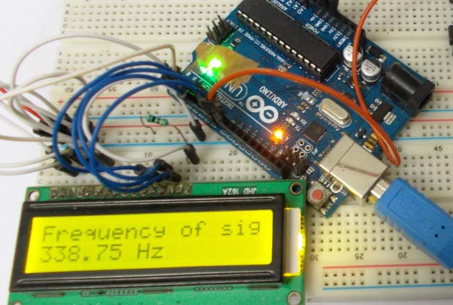
This project demonstrates how to build a cost-effective Frequency Counter using Arduino Uno capable of measuring signal frequencies up to 1 MHz. The frequency meter uses a Schmitt trigger gate (74LS14) to ensure accurate rectangular wave detection and displays the measured frequency on a 16×2 LCD display.
- ✅ Measures frequencies up to 1 MHz
- ✅ Cost-effective alternative to oscilloscopes
- ✅ Real-time frequency display on 16×2 LCD
- ✅ Built-in signal generator for testing (555 timer based)
- ✅ Schmitt trigger ensures accurate signal conditioning
- ✅ Simple and easy to build
| Component | Quantity | Description |
|---|---|---|
| Arduino Uno | 1 | Main microcontroller |
| 555 Timer IC | 1 | For signal generation |
| 74LS14 Schmitt Trigger | 1 | Signal conditioning |
| 16×2 LCD Display | 1 | Frequency display |
| 1kΩ Resistor | 2 | Circuit components |
| 100Ω Resistor | 1 | Circuit components |
| 47kΩ Potentiometer | 1 | Variable frequency control |
| 100nF Capacitor | 2 | Noise filtering |
| 1000µF Capacitor | 1 | Power supply filtering |
| Breadboard | 1 | Circuit assembly |
| Jumper Wires | As needed | Connections |
The frequency counter circuit consists of three main sections:
-
Signal Input & Conditioning: The input signal is passed through a 74LS14 Schmitt Trigger gate to ensure clean rectangular waveforms. This is crucial as Arduino can only detect square/rectangular waves accurately.
-
Arduino Processing: The Arduino Uno reads the signal on digital pin 8 using the
pulseIn()function, which measures both HIGH and LOW pulse durations to calculate frequency. -
LCD Display: A 16×2 LCD interfaced with Arduino displays the measured frequency in Hz in real-time.
For testing purposes, the project includes a 555 Timer Astable Multivibrator that generates a square wave with adjustable frequency:
- Formula:
Frequency (F) = 1.44 / ((RA + 2×RB) × C) - The 47kΩ potentiometer allows variable frequency output for comprehensive testing
- Output frequency can be adjusted by changing resistor and capacitor values
The 74LS14 Schmitt Trigger ensures:
- Conversion of any input waveform (sine, triangle, sawtooth) to clean rectangular waves
- Noise immunity through hysteresis
- Reliable digital signal for Arduino processing
The Arduino measures frequency using time-domain analysis:
-
Pulse Duration Measurement: The
pulseIn()function measures the duration of HIGH and LOW states of the input signalHtime = pulseIn(8, HIGH); // Measure HIGH pulse duration Ltime = pulseIn(8, LOW); // Measure LOW pulse duration
-
Period Calculation: Total time period = HIGH time + LOW time
Ttime = Htime + Ltime; // Total cycle time in microseconds -
Frequency Calculation: Frequency is the inverse of the time period
frequency = 1,000,000 / Ttime; // Convert to Hz
Since pulseIn() returns time in microseconds, we use 1,000,000 (1 second in microseconds) for the conversion.
#include <LiquidCrystal.h>

// Initialize LCD (RS, E, D4, D5, D6, D7)
LiquidCrystal lcd(2, 3, 4, 5, 6, 7);

// Variables for time and frequency measurement
int Htime;          // High time duration
int Ltime;          // Low time duration
float Ttime;        // Total time period
float frequency;    // Calculated frequency

void setup() {
  pinMode(8, INPUT);     // Set pin 8 as input for signal
  lcd.begin(16, 2);      // Initialize 16×2 LCD
}

void loop() {
  lcd.clear();
  lcd.setCursor(0, 0);
  lcd.print("Frequency of signal");

  // Measure HIGH and LOW pulse durations
  Htime = pulseIn(8, HIGH);
  Ltime = pulseIn(8, LOW);

  // Calculate total time and frequency
  Ttime = Htime + Ltime;
  frequency = 1000000 / Ttime;  // Frequency in Hz

  // Display frequency on LCD
  lcd.setCursor(0, 1);
  lcd.print(frequency);
  lcd.print(" Hz");

  delay(500);  // Refresh every 500ms
}| LCD Pin | Arduino Pin |
|---|---|
| RS | 2 |
| E | 3 |
| D4 | 4 |
| D5 | 5 |
| D6 | 6 |
| D7 | 7 |
| VSS | GND |
| VDD | +5V |
| V0 | Potentiometer (Contrast) |
- Pin 8: Frequency input (through Schmitt Trigger)
- Input: Signal from 555 timer or external source
- Output: Connected to Arduino Pin 8
- VCC: +5V
- GND: Ground
- Configured in astable mode for square wave generation
- Output connected to Schmitt Trigger input
- Frequency adjustable via 47kΩ potentiometer
-
Hardware Assembly:
- Connect the LCD to Arduino as per the pin connections table
- Build the 555 timer signal generator circuit on breadboard
- Connect the 74LS14 Schmitt Trigger between signal source and Arduino
- Add filter capacitors (100nF) across power rails
-
Software Upload:
- Open Arduino IDE
- Install
LiquidCrystallibrary (comes pre-installed) - Copy and paste the provided code
- Select Arduino Uno as board
- Select the correct COM port
- Upload the code
-
Testing:
- Power up the circuit
- Adjust the 47kΩ pot on the 555 timer to generate different frequencies
- Observe the frequency reading on the LCD display
- Measurement Range: 1 Hz to 1 MHz
- Best Accuracy: Below 707 Hz (1 Hz resolution)
- Audio Range: Suitable for audio frequency measurements, though resolution decreases at higher frequencies
- 10 kHz: Resolution approximately 100 Hz
- 100 kHz: Resolution approximately 11.1 kHz
- 1 MHz: Limited precision at this range
To measure frequencies beyond 1 MHz (e.g., RF signals):
- Add a pre-scaler circuit (e.g., 74HC4060)
- Modify code to multiply displayed frequency by pre-scale factor
- Useful for amateur radio applications (HF bands)
// Add calibration offset for crystal accuracy
frequency = (1000000 / Ttime) + calibration_offset;Implement multiple measurements and averaging to reduce fluctuations:
// Take average of multiple readings
for(int i = 0; i < 10; i++) {
  Htime += pulseIn(8, HIGH);
  Ltime += pulseIn(8, LOW);
}
frequency = 10000000 / (Htime + Ltime);int prescale = 1; // Set to prescaler division factor
frequency = (1000000 / Ttime) * prescale;- ✅ Audio Frequency Measurement: Testing audio circuits and oscillators
- ✅ Signal Generator Calibration: Verifying output frequencies of function generators
- ✅ Clock Signal Verification: Checking microcontroller and timer frequencies
- ✅ Education & Learning: Understanding frequency measurement principles
- ✅ Hobbyist Projects: DIY electronics testing and troubleshooting
- ✅ Amateur Radio: With prescaler, can measure HF bands (up to 30 MHz)
| Issue | Solution |
|---|---|
| No display on LCD | Check contrast pot, verify power connections |
| Inaccurate readings | Calibrate Arduino crystal, check Schmitt trigger operation |
| Frequency shows "inf" or 0 | Verify signal input on pin 8, check pulseIn timeout |
| Fluctuating readings | Implement averaging in code, add better filtering caps |
| 60 Hz interference | Ensure proper grounding, add shielding if necessary |
The pulseIn(pin, state) function is key to this project:
- Measures the duration (in microseconds) of a HIGH or LOW pulse
- Returns 0 if timeout occurs
- Maximum measurable pulse width depends on Arduino clock
- Cannot measure frequencies with very short pulse widths accurately
- Resolution decreases at higher frequencies
- Requires clean square/rectangular waves for best accuracy
- Schmitt Trigger essential for noisy signals
For detailed step-by-step instructions, circuit diagrams, and video demonstration, visit:
📘 Arduino Frequency Counter Circuit - CircuitDigest
- Arduino Waveform Generator
- 555 Timer IC Basics
- Arduino LCD Interfacing Tutorial
- Schmitt Trigger Circuit
- Arduino Projects
This project is open-source and available for educational and hobbyist purposes.
Project Source: CircuitDigest
Category: Microcontroller Projects
Difficulty Level: Intermediate
⭐ Star this project if you find it useful!
📧 For questions and support, visit CircuitDigest Forums