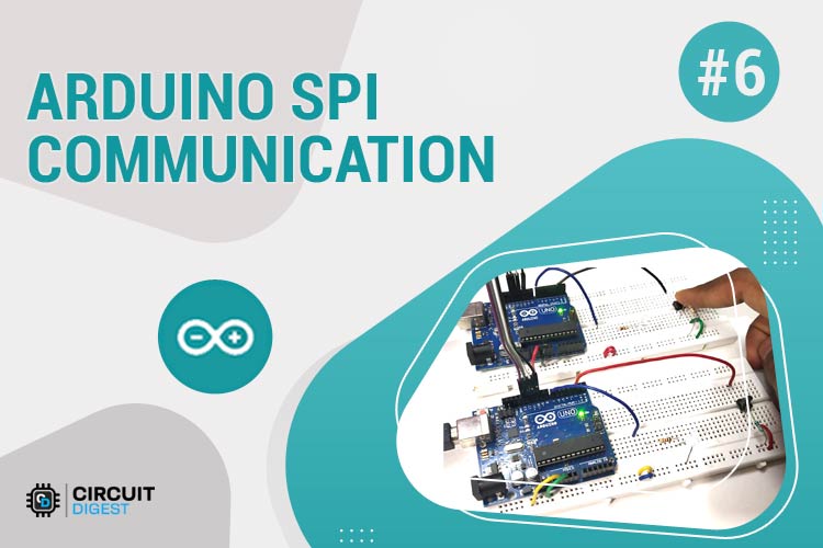
This project demonstrates SPI (Serial Peripheral Interface) communication between two Arduino boards. One Arduino acts as the Master and the other as the Slave, with cross-controlled LEDs and push buttons to showcase bidirectional data transfer using the SPI protocol.
- ✅ Full-duplex communication - Simultaneous data transfer in both directions
- ✅ High-speed data transfer - Up to 8MHz clock speed
- ✅ Synchronous protocol - Clock signal synchronizes data transfer
- ✅ Cross-device control - Master controls Slave LED and vice versa
- ✅ Real-time feedback - Serial monitor output for debugging
- Understanding SPI communication protocol fundamentals
- Arduino SPI library functions and implementation
- Master-Slave architecture setup
- Bidirectional data exchange between microcontrollers
- Interrupt-based communication handling
- SPI pin configuration and wiring
| Component | Quantity | Purpose |
|---|---|---|
| Arduino UNO | 2 | Master and Slave controllers |
| LED | 2 | Visual indicators |
| Push Button | 2 | Input controls |
| Resistor 10kΩ | 2 | Pull-down for buttons |
| Resistor 2.2kΩ | 2 | Current limiting for LEDs |
| Breadboard | 1 | Circuit assembly |
| Connecting Wires | Several | Circuit connections |
| SPI Signal | Arduino UNO Pin | Alternative Pin | Function |
|---|---|---|---|
| MOSI | 11 | ICSP-4 | Master Output, Slave Input |
| MISO | 12 | ICSP-1 | Master Input, Slave Output |
| SCK | 13 | ICSP-3 | Serial Clock |
| SS | 10 | Any Digital Pin | Slave Select |
- MOSI (Master Out Slave In) - Data line from Master to Slave
- MISO (Master In Slave Out) - Data line from Slave to Master
- SCK (Serial Clock) - Clock signal generated by Master
- SS (Slave Select) - Chip select signal (LOW = active)
- LED: Pin 7 (with 2.2kΩ resistor)
- Push Button: Pin 2 (with 10kΩ pull-down resistor)
- SPI Pins: 11 (MOSI), 12 (MISO), 13 (SCK), 10 (SS)
- LED: Pin 7 (with 2.2kΩ resistor)
- Push Button: Pin 2 (with 10kΩ pull-down resistor)
- SPI Pins: 11 (MOSI), 12 (MISO), 13 (SCK), 10 (SS)
Master Pin 11 (MOSI) ──→ Slave Pin 11 (MOSI)
Master Pin 12 (MISO) ←── Slave Pin 12 (MISO)
Master Pin 13 (SCK)  ──→ Slave Pin 13 (SCK)
Master Pin 10 (SS)   ──→ Slave Pin 10 (SS)
GND                  ──→ GND (Common Ground)
#include <SPI.h>

// Initialize SPI communication
SPI.begin();

// Set clock divider (speed control)
SPI.setClockDivider(SPI_CLOCK_DIV8);  // 2MHz on 16MHz Arduino

// Transfer data (bidirectional)
byte received_data = SPI.transfer(send_data);

// Attach interrupt for slave
SPI.attachInterrupt();-
Setup Phase:
- Initialize serial communication
- Configure I/O pins
- Begin SPI communication
- Set clock divider
- Set SS pin HIGH (idle state)
-
Main Loop:
- Read local button state
- Set SS LOW (start communication)
- Transfer data via
SPI.transfer() - Process received data
- Control LED based on slave input
- Set SS HIGH (end communication)
-
Setup Phase:
- Initialize serial communication
- Configure I/O pins
- Set MISO as OUTPUT
- Enable SPI in slave mode:
SPCR |= _BV(SPE) - Attach SPI interrupt
-
Interrupt Service Routine (ISR):
- Automatically triggered when data received
- Read data from SPDR register
- Set received flag
-
Main Loop:
- Process received data when flag is set
- Read local button state
- Send response data via SPDR register
- Master Initiates: Master reads its button and prepares data
- SS Activation: Master pulls SS line LOW to select slave
- Data Exchange:
SPI.transfer()sends and receives data simultaneously - Slave Response: Slave's ISR captures data and prepares response
- Cross Control: Master button controls Slave LED, Slave button controls Master LED
- Continuous Loop: Process repeats every second
- Connect Master Arduino to computer
- Upload Master code via Arduino IDE
- Disconnect and connect Slave Arduino
- Upload Slave code via Arduino IDE
- Connect both Arduinos as per circuit diagram
- Power both boards
- Open Serial Monitor for both (115200 baud)
- Press Master button → Slave LED lights up
- Press Slave button → Master LED lights up
- Master button pressed → Slave LED ON, Serial: "Slave LED ON"
- Master button released → Slave LED OFF, Serial: "Slave LED OFF"
- Slave button pressed → Master LED ON, Serial: "Master LED ON"
- Slave button released → Master LED OFF, Serial: "Master LED OFF"
| Problem | Solution |
|---|---|
| No communication | Check SPI wiring, ensure common ground |
| Erratic behavior | Reduce SPI speed, check pull-up/pull-down resistors |
| One-way communication | Verify MISO connection and slave ISR setup |
| LEDs always on/off | Check button wiring and resistor values |
- Use Serial Monitor to trace data flow
- Verify pin connections with multimeter
- Start with slower SPI clock speeds
- Ensure proper ground connections
This basic SPI setup can be extended for:
- Sensor Networks: Multiple sensors on single SPI bus
- Display Interfaces: TFT/OLED screen control
- Memory Devices: SD card and EEPROM interfacing
- Wireless Modules: NRF24L01, ESP8266 communication
- Industrial Control: Multi-device automation systems
- Master-Slave communication concepts
- Synchronous vs Asynchronous protocols
- Interrupt-driven programming
- Hardware abstraction layers
- Real-time embedded systems
- SPI protocol understanding
- Multi-device coordination
- Interrupt handling
- Serial debugging
- Circuit analysis
- Arduino SPI Library: Official Documentation
- SPI Protocol Specification: Motorola SPI Standard
Q: Can I use different Arduino models? A: Yes, but check the SPI pinout as it varies between models (Nano, Mega, etc.)
Q: What's the maximum SPI speed? A: Up to 8MHz on 16MHz Arduino, but 2-4MHz is recommended for stability
Q: Can I connect multiple slaves? A: Yes, use individual SS pins for each slave device
Q: Is level shifting needed for 3.3V devices? A: Yes, use level shifters when interfacing 5V Arduino with 3.3V SPI devices
Q: Why use SPI over I2C? A: SPI offers higher speeds, full-duplex communication, but requires more pins
This project is open-source and available under the MIT License. Feel free to modify and distribute.
Contributions are welcome! Please feel free to submit issues, suggestions, or pull requests to improve this tutorial.
Happy Learning! 🎓
Master the art of inter-microcontroller communication with this comprehensive SPI tutorial.