LED interfacing is the foundational project for anyone beginning their journey with microcontrollers and embedded systems. This project demonstrates how to interface an LED with the 8051 microcontroller (AT89S52) and program it to blink using Embedded C. The project teaches essential concepts like GPIO programming, port configuration, basic input-output operations, and hardware-software interaction.
Project Source: LED Interfacing with 8051 Microcontroller - Circuit Digest
- Understanding 8051 microcontroller architecture and pin configuration
- GPIO (General Purpose Input/Output) programming
- Port configuration and manipulation through software
- Implementing negative logic for LED control
- Delay generation using software loops
- Crystal oscillator integration for timing
- Basic embedded C programming for hardware control
| S.No | Component | Value/Type | Quantity | Purpose |
|---|---|---|---|---|
| 1 | Microcontroller | AT89S52 | 1 | Main processing unit |
| 2 | LED | 5mm (Red/Green) | 1 | Output indicator |
| 3 | Resistor | 330Ω | 1 | LED current limiting |
| 4 | Crystal Oscillator | 11.0592 MHz | 1 | Clock generation |
| 5 | Capacitor | 22pF | 2 | Crystal oscillation |
| 6 | Capacitor | 10µF | 1 | Reset circuit |
| 7 | Resistor | 10kΩ | 1 | Reset pull-up |
| 8 | Push Button | SPST | 1 | Manual reset |
| 9 | Power Supply | 5V DC | 1 | System power |
| 10 | Breadboard | Standard size | 1 | Circuit assembly |
| 11 | Connecting Wires | 22 AWG | As needed | Connections |
| Parameter | Specification | Description |
|---|---|---|
| Microcontroller | AT89S52 (8051 family) | 40-pin DIP package with 4 I/O ports |
| LED Connection | Port 1, Pin 0 (P1.0) | Any port pin can be used |
| Crystal Frequency | 11.0592 MHz | Standard frequency for serial communication |
| Logic Level | Negative Logic | 0 = LED ON, 1 = LED OFF |
| LED Resistor | 330Ω - 1kΩ | Current limiting resistor |
| Operating Voltage | 5V DC | Standard TTL voltage level |
| RAM | 256 Bytes | For variable storage during execution |
| Flash Memory | 8KB | For program storage (EEPROM) |
| Pin Number | Pin Name | Connection | Function |
|---|---|---|---|
| 40 | Vcc | +5V | Power supply positive |
| 20 | GND | Ground | Power supply ground |
| 1 | P1.0 | LED (cathode) | Digital output to LED |
| 18, 19 | XTAL2, XTAL1 | 11.0592MHz Crystal | Clock oscillator input |
| 31 | EA | Vcc | Internal memory enable (active low) |
| 9 | RST | Reset Circuit | System reset (active high) |
| 29 | PSEN | No connection | Program store enable (for external memory) |
| 30 | ALE | No connection | Address latch enable (for external memory) |
The AT89S52 has 4 ports (P0, P1, P2, P3), each with 8 pins:
- Each port can be considered as an 8-bit register from software perspective
- Each pin can be used for both input and output operations
- Some pins have dual functionality (interrupts, counters, timers)
- Port 1 is recommended for LED interfacing due to built-in pull-up resistors
LED Connection (Negative Logic):
- LED anode → Vcc (+5V) through 330Ω resistor
- LED cathode → Pin P1.0 (Pin 1) of AT89S52
- When P1.0 = 0 (LOW), LED turns ON
- When P1.0 = 1 (HIGH), LED turns OFF
Crystal Oscillator Circuit:
- 11.0592 MHz crystal connected between XTAL1 (Pin 18) and XTAL2 (Pin 19)
- Two 22pF capacitors connected from each XTAL pin to ground
- Provides clock pulses for timing calculations and synchronization
Reset Circuit:
- 10kΩ resistor connected between Vcc and RST (Pin 9)
- 10µF capacitor connected between RST and ground
- Push button in parallel with capacitor for manual reset
- Reset is active HIGH
Memory Configuration:
- EA (Pin 31) connected to Vcc for using internal memory
- PSEN (Pin 29) and ALE (Pin 30) left floating (not using external memory)
The 8051 microcontroller's output pins cannot source sufficient current (typically 1-2mA) to drive an LED effectively, but they can sink much more current (10-15mA). Therefore:
- The LED cathode connects to the microcontroller pin
- When the pin outputs LOW (0V), it acts as ground
- Current flows from Vcc → LED → Microcontroller pin → Ground
- This allows the LED to illuminate brightly
#include

// Delay function: generates delay in milliseconds
void delay(unsigned int y) {
    unsigned int i, j;
    for(i = 0; i < y; i++) {
        for(j = 0; j < 1275; j++) {
            // Empty loop for delay generation
        }
    }
}

void main() {
    while(1) {  // Infinite loop
        delay(100);    // Wait for 100ms
        P1_0 = 0;      // Turn LED ON (negative logic)
        delay(100);    // Wait for 100ms
        P1_0 = 1;      // Turn LED OFF (negative logic)
    }
}Header File:
#include <REGX52.h>- Includes basic register definitions for 8051
Delay Function:
- Uses nested for-loops to create time delay
delay(100)creates approximately 100ms delay- Inner loop runs 1275 times to generate ~1ms delay
Main Function:
while(1)creates an infinite loopP1_0 = 0turns LED ON (negative logic)P1_0 = 1turns LED OFF (negative logic)- LED blinks with 100ms ON and 100ms OFF intervals
How 1275 iterations produce 1ms delay:
-
Machine Cycle Time: One machine cycle in 8051 requires 12 crystal pulses
Machine Cycle Time = 12 / 11,059,200 Hz = 1.085 µs -
Delay Calculation:
Delay = 1275 iterations × 1.085 µs ≈ 1.38 ms ≈ 1 ms -
For 100ms delay:
Total Delay = 100 × 1 ms = 100 ms
Note: Exact timing depends on compiler optimisation and instruction overhead. Empirical testing shows 1275 iterations produce approximately 1ms delay.
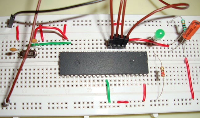
- Place the AT89S52 microcontroller on the breadboard
- Connect a 5V power supply to Pin 40 (Vcc) and Pin 20 (GND)
- Connect the 11.0592 MHz crystal between pins 18 and 19
- Add 22pF capacitors from each crystal pin to ground
- Build a reset circuit with a 10kΩ resistor and 10µF capacitor
- Connect EA (Pin 31) to Vcc
- Connect the LED cathode to P1.0 (Pin 1) through a 330Ω resistor
- Connect the LED anode to Vcc
- Install Keil µVision IDE or any 8051 C compiler
- Create new project and select AT89S52 device
- Write the embedded C code (provided above)
- Build the project to generate HEX file
- Check for compilation errors
- Use a programmer (USB ASP, ISP, or compatible programmer)
- Connect programmer to AT89S52 according to programmer specifications
- Load the generated HEX file into programming software
- Flash/burn the program into AT89S52's EEPROM
- Disconnect programmer
- Apply 5V power supply to the circuit
- Press reset button if LED doesn't start blinking
- LED should blink with 100ms intervals (ON/OFF)
- Verify negative logic operation
| Problem | Possible Cause | Solution |
|---|---|---|
| LED not glowing | Program not flashed correctly | Re-flash HEX file and press reset |
| LED always ON/OFF | Wrong logic or connection | Check negative logic wiring |
| No response | Power supply issue | Verify 5V at Vcc and GND pins |
| Irregular blinking | Crystal oscillator problem | Check crystal and capacitor values |
| Circuit not working | Reset pin floating | Ensure proper reset circuit |
| Programming error | Wrong connections | Verify programmer connections |
Interfacing an LED with the 8051 microcontroller involves connecting and controlling it through GPIO pins. The LED is connected via a current-limiting resistor to any port pin, and the pin is programmed to output HIGH or LOW logic levels to switch the LED ON or OFF.
Negative logic is used because the 8051's output pins can only source 1-2mA but can sink 10-15mA. In negative logic configuration, the LED cathode connects to the microcontroller pin. When the pin outputs LOW (0V), current flows from Vcc through the LED to ground, making it illuminate brightly.
Port 1 (P1) is the best choice because it has built-in internal pull-up resistors and doesn't require external components. All four ports can be used, but:
- Port 0 requires external pull-up resistors (10kΩ)
- Port 2 and Port 3 should be used carefully due to dual functions
The 11.0592 MHz crystal is commonly used because it's perfectly divisible by standard baud rates (9600, 4800, 2400 bps) with zero error in serial communication. For simple LED projects, other frequencies (12 MHz, 10 MHz, 16 MHz) can also be used.
Yes! You can connect up to 32 LEDs directly (8 LEDs per port × 4 ports). Each LED needs a current-limiting resistor. For more LEDs, use:
- LED driver ICs (ULN2003)
- Multiplexing techniques
- Shift registers (74HC595)
- Sink current: 15-20mA per pin (safe for LEDs)
- Source current: 1-2mA per pin (not enough for LEDs)
- Port maximum: 71mA total for all 8 pins
- Microcontroller maximum: 150mA total
Delay time = Loop iterations × Machine cycle time × Instructions per iteration

With 11.0592 MHz crystal:
- Machine cycle = 12 / 11,059,200 = 1.085 µs
- For 1ms delay ≈ 1275 iterations (empirically tested)
After completing this project, you will understand:
✅ 8051 Architecture - Pin configuration, memory structure, port operations
✅ GPIO Programming - Controlling individual pins through software
✅ Negative Logic Implementation - Current sourcing vs. sinking concepts
✅ Timing Generation - Software-based delay creation and calculation
✅ Crystal Oscillator Operation - Clock signal generation and timing
✅ Reset Circuit Design - Power-on-reset and manual reset implementation
✅ Embedded C Programming - Hardware-software interaction fundamentals
✅ Current Management - LED current limiting and port current limits
Once you master basic LED interfacing, you can extend the project:
- Multiple LED Patterns - Create running lights, chaser effects
- LED Matrix Display - Interface 8×8 LED matrix using MAX7219
- PWM Control - Implement LED brightness control using PWM
- Button Control - Add push buttons to control LED patterns
- Seven Segment Display - Extend to numeric displays
- Timer-Based Blinking - Use hardware timers instead of software delays
- NeoPixel Integration - Control addressable RGB LED strips
- Digital Notice Board - Create scrolling text using P10 LED panels
Explore more LED display projects:
- MAX7219 LED Dot Matrix Display with Arduino - Dynamic LED matrix displays
- WS2812B Neopixel LED Strip with Arduino - Addressable RGB LED control
- P10 LED Matrix Digital Notice Board - Professional-grade LED display boards
- Micro-controller Projects - Check out this projects
- Project Tutorial: Circuit Digest - LED Interfacing with 8051
- Getting Started: 8051 Microcontroller Basics
- AT89S52 Datasheet: Available from Microchip (formerly Atmel)
- Keil µVision IDE: For embedded C development
LED interfacing with 8051 microcontroller is the fundamental starting point for embedded systems development. This project provides hands-on experience with GPIO control, timing generation, negative logic implementation, and hardware-software interaction. The knowledge gained from this simple LED interfacing forms the foundation for more complex projects like motor control, sensor interfacing, display systems, and communication protocols.
Whether you're a beginner exploring embedded systems or advancing to sophisticated microcontroller applications, mastering LED interfacing with 8051 is an essential stepping stone in your electronics journey.
This project is for educational purposes. Please refer to the source at Circuit Digest for complete information.
Happy Learning! 🚀
Master the basics today, build innovative embedded systems tomorrow!