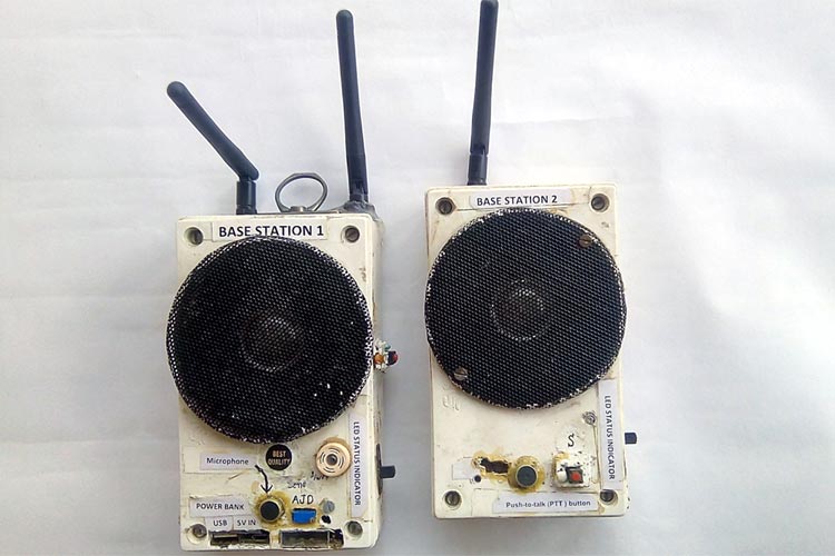
This project demonstrates how to build a long-range wireless communication system using Arduino and nRF24L01 RF modules. The walkie talkie system enables real-time voice communication between multiple devices (up to 6 units) with a range of up to 1 kilometer using external antennas.
Project Source: Circuit Digest - Arduino Walkie Talkie using nRF24L01
- Long Range Communication: Up to 1km range with nRF24L01+PA+LNA and external antenna
- Multi-device Support: One module can communicate with up to 6 other modules simultaneously
- Low Power Consumption: Optimized for battery-powered portable operation
- Push-to-Talk (PTT) Operation: Simple button press for transmission control
- No Interference: Uses 2.4GHz ISM band with 125 independent channels
- Real-time Audio: Low latency voice transmission and reception
- Construction site communication
- Security personnel coordination
- Outdoor adventure groups
- Emergency communication systems
- Smart helmet communication for bikers
- Industrial facility coordination
- nRF24L01+PA+LNA with external 2dB antenna (2 pieces)
- Arduino UNO or compatible microcontroller (2 pieces)
- Audio amplifier PAM8403 stereo module (2 pieces)
- Microphone circuit or sound sensor module (2 pieces)
- 4-inch loudspeaker 8-ohm (2 pieces)
- Li-ion batteries 3.7V (4 pieces - 2 sets)
- TP4056 charging modules with protection (2 pieces)
- DC-DC step-up booster modules 2A (2 pieces)
- AMS1117 3.3V voltage regulator modules (2 pieces)
- Push button for PTT functionality (2 pieces)
- LED indicators for power status (2 pieces)
- Resistors: 470Ω (2), 1kΩ (2)
- Capacitors: 104pF (2), 100nF (4)
- 2N3904 NPN transistor for microphone circuit (2)
- Jumper wires, headers, vero board
- Enclosure for portable assembly
The complete circuit integrates:
- nRF24L01+PA+LNA module with 3.3V regulated power supply
- Custom microphone amplifier circuit using 2N3904 transistor
- PAM8403 stereo audio amplifier for speaker output
- PTT button with debouncing capacitor
- Power management system with Li-ion batteries
nRF24L01 to Arduino:
- CE → Digital Pin 7
- CSN → Digital Pin 8
- SCK → Digital Pin 13
- MOSI → Digital Pin 11
- MISO → Digital Pin 12
- IRQ → Digital Pin 2
- VCC → 3.3V (via AMS1117 regulator)
- GND → Ground
Audio System:
- Microphone → Analog Pin A1
- Audio Output → Digital Pins 9 & 10 → PAM8403 → Speaker
- PTT Button → Digital Pin 3 (with interrupt)
- Flash Arduino bootloader to ATmega328P
- Add 16MHz crystal oscillator
- Upload the walkie talkie code
- Connect nRF24L01 as per circuit diagram
- Use AMS1117 3.3V regulator for stable power supply
- Add 100nF decoupling capacitor on VCC and GND
- Build simple transistor amplifier using 2N3904
- Alternative: Use commercial sound sensor module
- Connect output to Arduino analog pin A1
- Connect PAM8403 stereo amplifier
- Input from Arduino pins 9 & 10
- Output to 4-inch 8-ohm speaker
- Use single channel (right) for mono operation
- Add push button with 104pF debouncing capacitor
- Connect to Arduino pin 3 with interrupt capability
- Include 1kΩ pull-up resistor
- Use 2 Li-ion batteries in series for each unit
- Integrate TP4056 charging modules with protection
- Add DC-DC boost converter for stable 5V supply
- Include power indicator LEDs
- Mount all components in weatherproof enclosure
- Ensure proper antenna positioning for maximum range
- Add charging ports and status indicators
#include <RF24.h>
#include <SPI.h>
#include <RF24Audio.h>
#include "printf.h"RF24 radio(7,8); // CE, CSN pins
RF24Audio rfAudio(radio,0); // Radio instance, device ID
int talkButton = 3; // PTT button pin
void setup() {
Serial.begin(115200);
radio.begin();
rfAudio.begin();
pinMode(talkButton, INPUT);
attachInterrupt(digitalPinToInterrupt(talkButton), talk, CHANGE);
rfAudio.receive(); // Default to receive mode
}
void talk() {
if (digitalRead(talkButton))
rfAudio.transmit(); // PTT pressed - transmit
else
rfAudio.receive(); // PTT released - receive
}
void loop() {
// Main loop remains empty
// All functionality handled by interrupts
}| Parameter | Specification |
|---|---|
| Operating Frequency | 2.4GHz ISM Band |
| Data Rates | 250kbps, 1Mbps, 2Mbps |
| Range (Outdoor) | Up to 1000m with external antenna |
| Range (Indoor) | 100-200m depending on obstacles |
| Channels | 125 independent channels |
| Multi-device Support | Up to 6 receiving units |
| Power Consumption | Low power, suitable for battery operation |
| Battery Life | 8-12 hours active, 24-48 hours standby |
| Method | Improvement | Implementation |
|---|---|---|
| External Antenna | 10x range increase | Use 2.4GHz directional antenna |
| Power Amplifier | 5x power boost | nRF24L01+PA+LNA module |
| Clear Line of Sight | 3x effective range | Optimal positioning |
| Ground Plane | 2x signal stability | Proper PCB design |
No Audio Reception:
- Check 3.3V power supply stability
- Verify nRF24L01 connections
- Ensure proper antenna connection
Poor Audio Quality:
- Add noise filtering capacitors
- Use shielded cables for audio connections
- Improve microphone circuit design
Short Range:
- Use nRF24L01+PA+LNA modules
- Position antennas for line-of-sight
- Check for interference sources
Power Issues:
- Verify battery voltage levels
- Check charging module functionality
- Monitor current consumption
- Use proper Li-ion battery protection circuits
- Ensure voltage regulators are correctly rated
- Implement overcurrent protection
- Use weatherproof enclosures for outdoor use
- Add LCD display for channel selection
- Implement encryption for secure communication
- Add GPS coordinates transmission
- Battery level monitoring and low battery alerts
- Multiple channel scanning capability
Q: What is the maximum range achievable? A: With nRF24L01+PA+LNA and external antenna in clear line-of-sight conditions, up to 1 kilometer is possible. Indoor range is typically 100-200 meters.
Q: Can multiple walkie talkies operate simultaneously? A: Yes, the nRF24L01 supports 125 unique channels. Each group can operate independently without interference.
Q: What programming knowledge is required? A: Basic Arduino programming knowledge is sufficient. The RF protocols are handled by libraries, requiring only digital I/O and interrupt programming.
Q: How long does the battery last? A: With 2000mAh Li-ion batteries, expect 8-12 hours of mixed use and 24-48 hours on standby.
Q: Is the circuit waterproof? A: The electronic components require a weatherproof enclosure (IP65 rated) for outdoor use with proper sealing for ports.
This project is based on the tutorial from Circuit Digest.
Educational Use: This project is intended for educational and hobbyist purposes. Ensure compliance with local RF regulations.
Power Limits: High-power modifications may require amateur radio licensing depending on local regulations.
Contributions to improve the design, code, or documentation are welcome. Please ensure all modifications maintain the educational focus and safety standards of the original project.
Project Difficulty: Intermediate
Estimated Build Time: 8-12 hours
Cost: $50-80 per unit (excluding enclosure)
Skills Required: Basic electronics, Arduino programming, PCB assembly