Project Type: Arduino Project

- Interface the OV7670 camera with Arduino UNO to capture low-resolution image data.
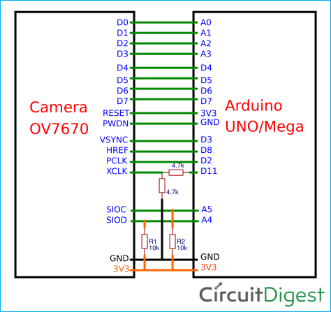
- Learn the role of VSYNC, HREF, and PCLK sync signals and the 8-bit data bus (D0–D7).
- Initialize OV7670 registers over SCCB (I²C-like) and generate XCLK from Arduino.
- Practical, memory-aware capture routines suitable for UNO constraints.
- Clear wiring, timing, and troubleshooting guidance.
| Component | Qty | Description |
|---|---|---|
| Arduino UNO (or MEGA 2560) | 1 | 16 MHz MCU; MEGA offers more RAM & pins (optional but helpful) |
| OV7670 Camera Module (no FIFO) | 1 | VGA (640×480) CMOS camera, 8-bit parallel output |
| Logic Level Converter (5V↔3.3V) | 1 | Recommended to protect the 3.3 V OV7670 lines |
| Jumper Wires (Male–Female) | As req. | For data, clock, and control lines |
| Breadboard | 1 | For prototyping connections |
| External 3.3 V Supply (optional) | 1 | Stable 3.3 V rail for the camera (if Arduino’s 3.3 V is insufficient) |
| USB Cable | 1 | Power and programming for Arduino |
- Clock & Power: The OV7670 requires a driving clock (XCLK, typically ~8–16 MHz) and 3.3 V power. Arduino can generate XCLK (e.g., via Timer1 PWM) at a lower rate suitable for experimentation.
- Register Setup (SCCB): Arduino configures the camera over SCCB (I²C-like on SIOD/SIOC) to set resolution, color format (e.g., RGB565/YUV), and timing.
- Frame Sync Signals: On each frame, VSYNC indicates frame start, HREF indicates valid line data, and PCLK clocks each pixel byte on D0–D7.
- Data Capture: Arduino samples D0–D7 on each PCLK when HREF is high. Given UNO’s RAM limits, sketches typically read partial frames, sub-sample, or stream data out (e.g., Serial).
- Display/Save: The captured bytes can be visualized on a host PC (via Serial viewer) or forwarded to external storage (SD card) if using a board with more memory or a FIFO-equipped camera.
Notes & Tips
- Voltage levels: OV7670 is a 3.3 V device. Use a bidirectional level shifter for Arduino UNO’s 5 V GPIO where necessary.
- XCLK source: Use a timer/PWM pin to feed XCLK to the camera’s clock input (exact pin depends on your sketch).
- Clean wiring: Keep PCLK, HREF, VSYNC, and data lines short and tidy to reduce noise.
| Symptom | Likely Cause | Recommended Fix |
|---|---|---|
| No image / all zeros | Missing/incorrect XCLK or power | Verify XCLK generation, 3.3 V supply, and camera GND reference |
| Random noise / unstable image | Long wires / signal integrity issues | Shorten wires, add common ground, ensure solid 3.3 V, consider small series R |
| Frame never starts | Wrong SCCB address or init sequence | Re-check SIOD/SIOC wiring; verify init registers and timing |
| Garbled colors | Wrong pixel format / byte order | Align Arduino capture code with selected format (RGB565, YUV) |
| Partial lines / tearing | Sampling off-edge of PCLK | Sample on correct PCLK edge; adjust timer prescalers or code timing |
| Camera warms or resets randomly | 3.3 V rail droop | Provide a stable 3.3 V source; decouple close to the camera module |
- Entry-level computer vision experiments on microcontrollers
- Line following / simple robotics with visual cues
- Image capture streaming to PC for educational demos
- Low-resolution motion detection prototypes
- Use an OV7670 + FIFO module for full-frame buffering
- Add SD card storage or stream over UART/USB to host software
- Migrate to ESP32/Raspberry Pi for higher throughput & real-time viewing
- Apply basic image processing (thresholding, edge detection) on MCU/PC
| Parameter | Detail |
|---|---|
| Camera Sensor | OmniVision OV7670 |
| Max Resolution | VGA (640×480) |
| Output Formats | RGB565, YUV, Bayer |
| Data Interface | 8-bit parallel (D0–D7) |
| Control Interface | SCCB (I²C-like) |
| Sync Signals | VSYNC, HREF, PCLK |
| Operating Voltage | 3.3 V (logic & core) |
| Typical XCLK | ~8–16 MHz (experimentally lower for UNO) |
| Host MCU | Arduino UNO (ATmega328P @ 16 MHz) |
- Main tutorial: OV7670 Camera Module with Arduino
- Arduino IDE Download (Official): https://www.arduino.cc/en/software
- OV7670 Datasheet (PDF): https://www.voti.nl/docs/OV7670.pdf
- Arduino Wire (I²C) Reference: https://www.arduino.cc/reference/en/language/functions/communication/wire/
- Example Codebase – OV7670 on Arduino UNO (No RAM/FIFO): https://github.com/ComputerNerd/ov7670-no-ram-arduino-uno
If this project helped you, please ⭐ star the repo and share it with fellow makers!
© CircuitDigest – Connecting Engineers and Makers
Your electronics projects, simplified.
🔖 Keywords: OV7670 OV7670 Arduino Arduino camera RGB565 YUV VSYNC HREF PCLK SCCB I2C 8-bit parallel camera Arduino UNO low-resolution image capture