This project demonstrates how to interface an A4988 Stepper Motor Driver Module with an Arduino UNO to precisely control a bipolar stepper motor such as the NEMA 17. The A4988 allows microstepping, adjustable current control, and supports supply voltages up to 35V with a maximum output of 2A per coil. Whether for a 3D printer, CNC machine, or robotics project, this tutorial covers pinouts, wiring connections, programming, and troubleshooting.
- Control bipolar stepper motors with precision
- Adjustable microstepping: Full, 1/2, 1/4, 1/8, and 1/16 steps
- Current limiting via onboard potentiometer
- Operates from 8V to 35V motor supply voltage
- Overcurrent and thermal protection built-in
- Compatible with both 3.3V and 5V logic
- Simple two-pin control: STEP and DIR
| Component | Description |
|---|---|
| Arduino UNO | Main microcontroller |
| A4988 Stepper Motor Driver | Motor driver module |
| Bipolar Stepper Motor | e.g., NEMA 17 |
| External Power Supply | 8–35V DC (e.g., 12V) for motor |
| 100µF Capacitor | Between VMOT and GND to prevent voltage spikes |
| Breadboard & Jumper Wires | For prototyping and connections |
| Heatsink (optional) | For cooling the A4988 under high current loads |
-
Power Delivery:
- VMOT pin supplies motor voltage (8–35V)
- VDD pin powers A4988 logic (3.3–5.5V) from Arduino
-
Control Signals:
- STEP pin receives pulses to move the motor
- DIR pin controls rotation direction
- MS1–MS3 pins set microstepping resolution
-
Motor Driving:
The A4988 energizes coils in a precise sequence based on received pulses, enabling accurate position control. -
Current Limiting:
Adjust the potentiometer to prevent overheating and match motor specifications.
-
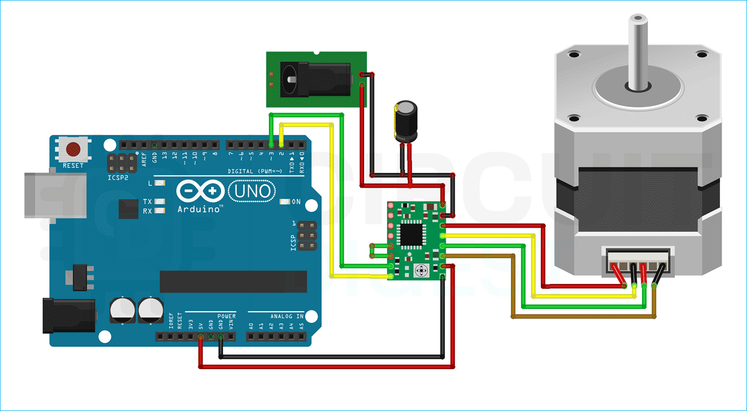
Power:
- VDD → 5V on Arduino
- GND → Arduino GND
- VMOT → External motor supply (e.g., 12V)
- 100µF capacitor between VMOT and GND
-
Control Pins:
- STEP → Arduino D3
- DIR → Arduino D2
-
Motor Output:
- Connect motor coils to 1A, 1B, 2A, 2B according to datasheet
| MS1 | MS2 | MS3 | Microstep Resolution |
|---|---|---|---|
| Low | Low | Low | Full Step |
| High | Low | Low | Half Step |
| Low | High | Low | Quarter Step |
| High | High | Low | Eighth Step |
| High | High | High | Sixteenth Step |
const int dirPin = 2;
const int stepPin = 3;
const int stepsPerRevolution = 200;

void setup() {
    pinMode(stepPin, OUTPUT);
    pinMode(dirPin, OUTPUT);
}

void loop() {
    // Clockwise rotation
    digitalWrite(dirPin, HIGH);
    for (int x = 0; x < stepsPerRevolution; x++) {
        digitalWrite(stepPin, HIGH);
        delayMicroseconds(1000);
        digitalWrite(stepPin, LOW);
        delayMicroseconds(1000);
    }
    delay(1000);

    // Counterclockwise rotation
    digitalWrite(dirPin, LOW);
    for (int x = 0; x < stepsPerRevolution; x++) {
        digitalWrite(stepPin, HIGH);
        delayMicroseconds(500);
        digitalWrite(stepPin, LOW);
        delayMicroseconds(500);
    }
    delay(1000);
}
| Issue | Cause / Solution |
|---|---|
| Motor not moving | Check wiring, ensure correct coil pairing, verify STEP and DIR signals |
| Overheating | Lower current limit via potentiometer, add heatsink |
| Erratic movement | Secure connections, check for noise interference |
| Driver shutting down | Ensure cooling, verify power supply current capacity |
- 3D Printers
- CNC Machines
- Camera Sliders
- Robotics
- Automated Positioning Systems
| Parameter | Specification | Notes |
|---|---|---|
| Motor Supply Voltage | 8V to 35V | Higher voltage improves torque & speed |
| Logic Voltage | 3.3V to 5.5V | Compatible with Arduino |
| Max Current per Coil | 2A | Requires adequate heat dissipation |
| Microstepping | Full, 1/2, 1/4, 1/8, 1/16 | Set via MS1–MS3 pins |
| Step Frequency | Up to 200kHz | Depends on supply voltage and load |
| Protection | Overcurrent, Thermal shutdown | Automatic fault handling |
| Sleep Current | <1mA | Ultra-low power mode |
If you found this helpful, please ⭐ star this repository and share it with others!
Built with 💡 by Circuit Digest
Making Electronics Simple
Arduino A4988 stepper motor microstepping driver NEMA 17 control
STEP DIR interface CNC positioning 3D printer motor control
Embedded C Arduino project A4988 pinout wiring motor driver tutorial