Example: FM Radio Demodulation
WORK IN PROGRESS
TODO thanks to dutra, darkknight, Deepwave

Files for this demo can be found in examples/sdr.
RF samples flow from the radio front end through the data path and are finally output as audio samples.
- Radio tuned center on FM station
- FIR and decimate down to ~300KSPS needed for FM channel, ~150KHz frequency range.
- Demodulate FM signal, still ~300KSPS, raw FM signal (has mono+stereo+etc)
- FIR and decimate down to 15KHz band for mono audio, output 48KSPS audio.
- FM radio deemphasis, flatten high freq
The specific rates and filtering required for the target SDR platform are as follows:
- IQ from radio: 125MSPS
- 125MSPS decimation by D=500 to 250KSPS
- 3 decimation stages=[5,10,10]
- FM Demodulation using differentiator
- Mono audio decimation
- 250KSPS interpolate by N=24 = 6MSPS
- then decimate by M=125 = 48KSPS
- stages=[5,5,5 # reuse 5x decim]
- Skipped FM radio deemphasis for now...
- SDR platform requires output of 32 bits each cycle
- two 16b samples buffer is not shown in diagrams
TODO cmd line for building with --top TODO top level .sv file instance of pipelinec top TODO summary of DWD sandbox build
- FIR filters were designed with a transition width ~= 1/3 of band
- Stopband + transition width all fall WITHIN the Nyquist freq
-
http://t-filter.engineerjs.com/
- Helper script to calculate values for
t-filter
- Helper script to calculate values for
def print_fir_config(fs, decim_factors):
  for d in decim_factors:
    bw_in = fs/2
    fs_out = fs/d
    bw_out = fs_out/2
    tw = bw_out/3
    pass_width = bw_out-tw
    stop = bw_out
    print(fs,"Hz decim by",d)
    print("pass",0,"Hz->",pass_width,"Hz","tw",tw)
    print("stop",stop,"Hz->",bw_in,"Hz")
    fs = fs_out

print_fir_config(125e6, [5,10,10])
print_fir_config(6e6, [5,5,5])
print_fir_config(6e6, [24])Building blocks of the design can be found in fm_radio.h. The top level using those components comes together in fm_radio_datapath() in fm_radio.c.
The data path consists of decimation and interpolation FIR filters, FM demodulation, and FM deemphasis.
fm_radio.h uses dsp/fir_decim.h, dsp/fir_interp.h, and the base dsp/fir.h header to declare various FIR filter configurations.
These header files are used with 'arguments' as if invoking a macro. For example, declaring a FIR filter function called my_fir looks like:
#define fir_name my_fir
#define FIR_N_TAPS 4
#define FIR_LOG2_N_TAPS 2 // log2(FIR_N_TAPS)
#define fir_data_t uint16_t
#define fir_coeff_t uint8_t
#define fir_out_t uint26_t // data_width + coeff_width + log2(taps#)
#define FIR_COEFFS {1, 2, 3, 4}
#include "dsp/fir_decim.h"
See examples/fir.c for more syntax.
dsp/fir_decim.h is a header that is included as if invoking a macro. The decimation by N design includes a shifting window of samples, every N cycles the low pass FIR filter function is applied to the window and a single sample is output.
dsp/fir_interp.h is a header that is included as if invoking a macro. The interpolation by N design first inserts N-1 zeros into the data stream (increasing sample rate). Then this stream of pulses surrounded by zeros is filtered using a low pass FIR to smoothly interpolate an output signal.
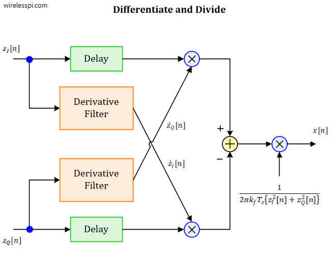
The fm_demodulate() function defined in fm_radio.h implements demodulation via differentiation and
could be written like so:
i16_stream_t fm_demodulate(ci16_stream_t iq_sample){
  static ci16_t iq_history[3];
  static ci16_t iq_dot;
  static int16_t output;
  if(iq_sample.valid){
    // save input
    iq_history[0].real = iq_sample.data.real;
    iq_history[0].imag = iq_sample.data.imag;
    // Calculate derivative
    iq_dot.real = iq_history[0].real - iq_history[2].real;
    iq_dot.imag = iq_history[0].imag - iq_history[2].imag;
    // Calculate output (I[1] * Q') - (Q[1] * I') w/ fixed point correction
    output = (iq_history[1].real * iq_dot.imag) >> 15;
    output -= (iq_history[1].imag * iq_dot.real) >> 15;
    // update history & return
    iq_history[1] = iq_history[0];
    iq_history[2] = iq_history[1];
  }
  // Output scaling factor
  float df = FM_DEV_HZ/SAMPLE_RATE_HZ;
  float scale_factor_f = 1.0 / (2.0 * 3.14 * df); // 1/(2 pi df)
  float f_i16_max = (float)(((int16_t)1<<15)-1);
  int32_t scale_factor_qN_15 = (int32_t)(scale_factor_f * f_i16_max);
  int16_t scaled_output_q1_15 = (output * scale_factor_qN_15) >> 15;
  i16_stream_t output_stream = {
    .data = scaled_output_q1_15,
    .valid = iq_sample.valid
  };
  return output_stream;
}
Note that in the final design, the demodulation function was modified to not include the output scaling factor, and to isolate the static registers into a separate window function for autopipelining.
TODO
Individual components have been simulated: decimation, interpolation, and demodulation.
The files in the test bench tb/ directory have been setup for testing a single component at a time, ex: the demodulation function alone.
tb.c consists of a single MAIN function wrapping the module to be tested. The test bench is configured with a set of input samples from a header file:
  #include "samples.h"
...
  static in_data_t i_samples[I_SAMPLES_SIZE] = I_SAMPLES;
  static in_data_t q_samples[Q_SAMPLES_SIZE] = Q_SAMPLES;
  static uint1_t samples_valid[SAMPLES_VALID_SIZE] = SAMPLES_VALID;
And the function under test returns output samples that are printed to screen:
  // Print valid output samples
  if(i_output.valid & q_output.valid){
    printf("Cycle,%d,Sample IQ =,"out_data_format","out_data_format"\n", cycle_counter, i_output.data, q_output.data);
}compare_samples.py generates input samples into "samples.h" and compares output by parsing the sim_output.log samples printed to screen during simulation.
From in tb/ directory, the following is an example command line that will: clear previous output, generate input samples, run simulation using those samples, save log of output samples, and finally parse+display+compare the expected vs. simulation output waveforms.
rm sim_output.log; python3 compare_samples.py && ../../../src/pipelinec tb.c --sim --comb --cocotb --ghdl --run 123 &> sim_output.log && python3 compare_samples.pyTODO commit python script using soapy api Hear audio? :)
TODO CIC filters, combining/multiplexing multiple decim FIRs (ex. I and Q)...
How to deal with flow control needed for more complicated interpolation? Ex. if back-to-back interpolation is needed then stalling/flow control pushing back into data path is required. Currently data path is free flowing with valid flag - but no ready flag to push back flow control exists.