Welcome to Purdue Robomaster Club's Electrical System Repository Created by Chengming Zhang. This repository contain everything from PCB design, Design Notebook (In sub-folder's ReadMe.md), and softwares.
If you are not familier with Robomaster, or Purdue's Robomaster Team, please refer to Our Website or check out this video covered by The Verge.
Electrical Team Lead: Chengming Zhang @cmz97
Active Member:
Henry Silva @Lazloian
Dansen Wang @cmz97
MingCheng Li @blaticslm
Ben Mirvish @bmivish
📣For detail design notebook, pls visit the coresponding directory📣
🔜 Future Project
🉑 Completed Project
🔂 New Iteration
🚮 Abanded Project
The image bellow is our latest Electrical System Diagram which lays out all the connection between our subsystems.

Made by @bmirvish @blaticslm
Due to the competition rule, the robot chassis, which consists of four DJI 3508 geared brushless motor, can not draw more than 240W of power at any given time. To overcome this limitation, we designed our custom made supercapacitor bank as a buffer that provides instantaneous power to our robot on demand. This Capacitor Bank only consist of voltage banlancing circuit, ADC, and the Super Capacitor Unit. Since this is a passive electrical unit, there is no firmware.
Plan for your PCB, Electrical Parameter and Mechinical Parameters like dimentions in your own folder
‼️
- PCB Design @#todo
‼️ - CAD Design Enclosure @#google drive link
‼️
Made by @cmz97
Since Capacitor is a short circuit when not charged, we need to design a consitance current charger to avoid damage of the battery and capacitor. Chengming Selected to use a H bridge Configuration to create a custon buck convertor using STM32F334. Currently, the Super Capacitor Charger can takes any voltage between 5v - 50v and convert it to 1v - 40v. The maxium output current is 10A. The PCB has a dimension of 2.599 in x 2.487 in and four layer.
PCB Design @SuperCapacitor-v2.0
Firmware @SuperCapacitor-v2.0
Power Distribution Board is used to distribute electrical current in different voltage across the robot. Currently the Robot takes the following voltage level.
24 Volt for Robot controller, Any motor
12 Volt for Jetson TX 2, Transparent OLED
5 Volt for Gimbal Electrical Controller Board (ATMEGA), Electrical System Controller(ESP32)
3.3 Volt for all the embedded chip, STM32F4, ESP32, ATMEGA
1.5 Volt for Ammo remaining detection circuit
For a more accurate and compelete report on voltage and current usage of our robot, pls refer to Power Distribution Board Design Log
The newst power distribution board is divided into three seperated board:
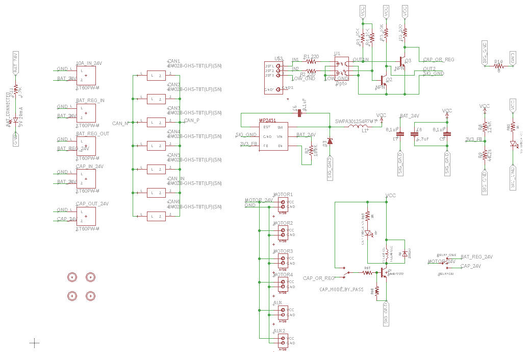
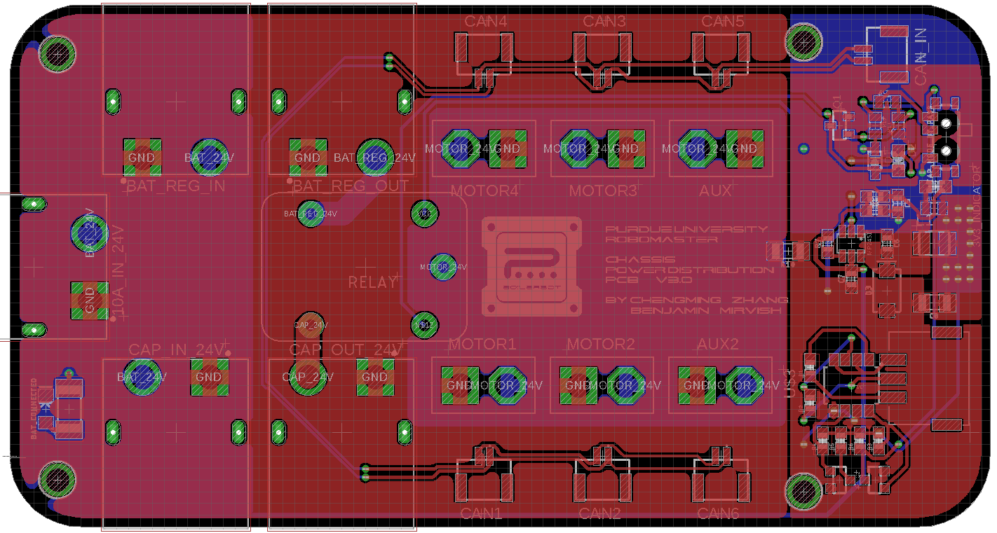
Made by @cmz97
This board provides all the power delivery on the robot chassis, which consist of four DJI M3508 Motor. It also has a 3.3v relay on board that selection output from either the super capacitor bank or the battery directorly. This switching action can be controlled by software via a logic high, which is passed through a opto-isolator for signal isolation. In case of emergency, such as super capacitor failure, one can flip a by-pass switch that disable all software input, and force the circuit to take battery input only.
The software switch is controlled by the Electrical System Controller (STM32/ESP32) that switch the output dynamically according to the current power usage. In seniorio such as low votage on super capacitor, Electrical System Controller can select battery input to avoid damage to the supercapacitor, and left it for charging.
Chassis Power Distribution Board Repository for Detail Info
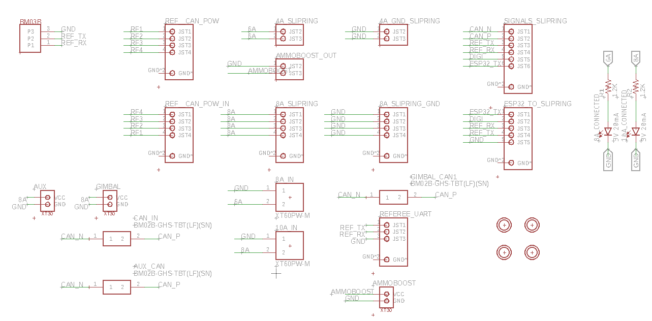
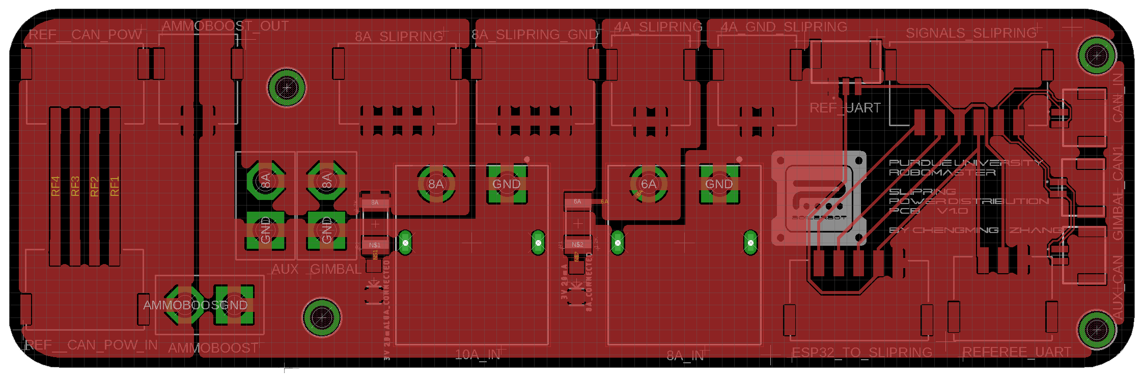
Made by @cmz97
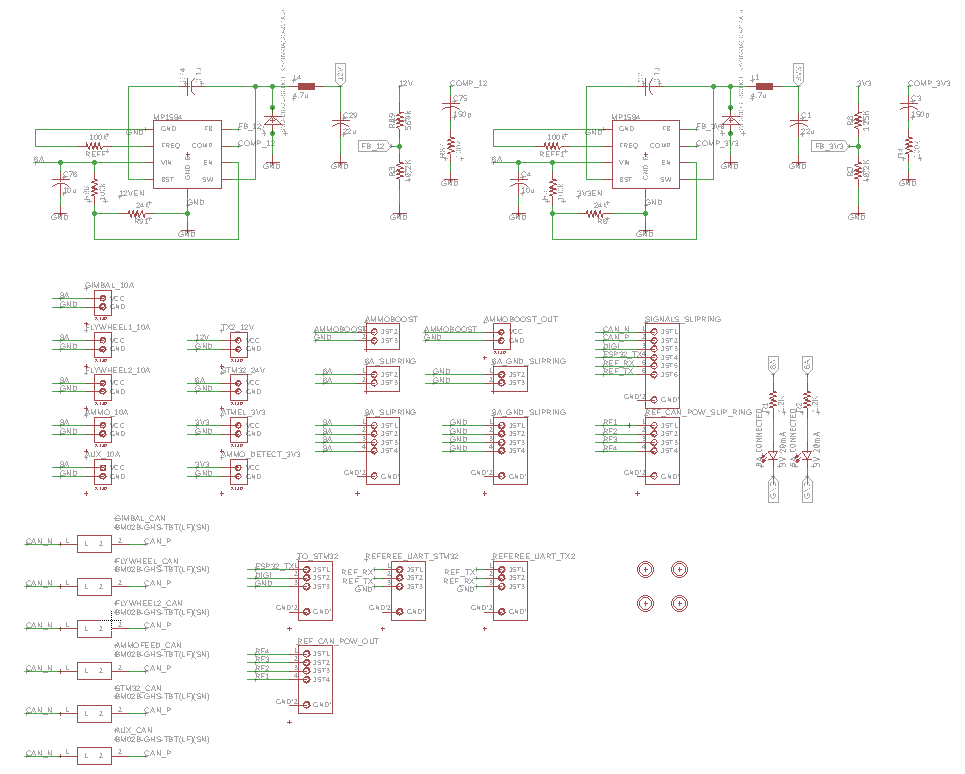
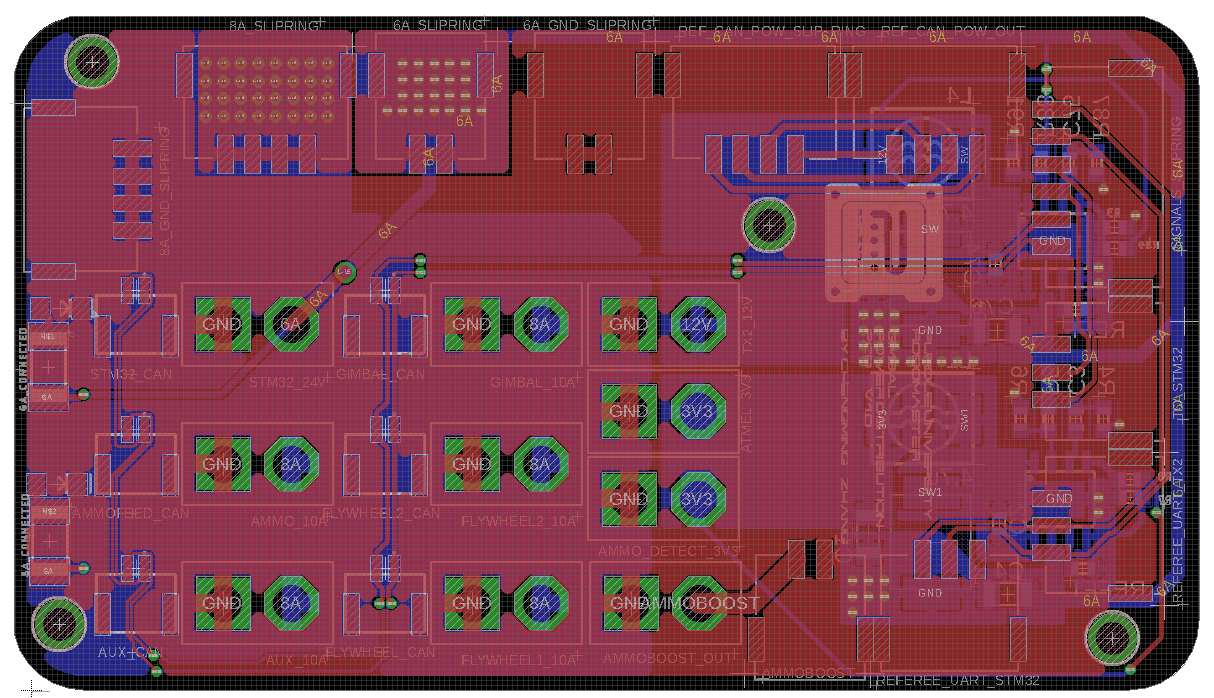
This board provides power to the Pitch Motor for the gimbal system, as well as power for Electrical System Controller. The board also provides pre-organization of the wires that go up through the slip-ring. Slipring is used in the robot due to mechanical constraints, where the robot's gimbal needs to rotate continuously. Since there are only 24 wires passess through the slipring used in our standard robot, with each of the wire capable of carring 2A of maxium continouse current, proper signal allocation need to be conducted.
We concluded the following wiring asssignment:
| Signal Name | 8A Power | 8A GND | 4A Power | 4A GND | Motor CAN H | Motor CAN L | REF_TX | REF_RX | GPIO | ESP32_TX | Referee System | Ammo Boost |
|---|---|---|---|---|---|---|---|---|---|---|---|---|
| # of Wire | 4 | 4 | 2 | 2 | 1 | 1 | 1 | 1 | 1 | 1 | 4 | 2 |
| Max Current (A) | 8 | 8 | 4 | 4 | 2 | 2 | 2 | 2 | 2 | 2 | 2 | 2 |
SlipRing Distribution Board Repository for Detail Info
Made by @cmz97
This board provides power to the STM32 Robot controller, JetsonTX2, Yall Motor, Flywheel, ammo motor, as well as the Gimbal Electrical System Controller. On board this board, there are two MP1584EN buck convertor that converts 24v from the battery to 12v for Tx2 and 5v for the Gimbal Electrical System Controller.
Robomater Gimbal Power Distribution Board Repository for Detail Info
-
PCB Design
Made by @cmz97 -
Firmware
Made by @William-An
Made by @cmz97
Made by @Lazloian
System Controller uses a transparent OLED in front of the driver's camera to display information to the driver. Board recieves info from ammo detector and tof sensors
HUD Info
-
Lines on the sides indicate walls that are close to the robot
-
Cross hairs in the center of the screen indicate low ammo in the hopper
Made by @Lazloian