Explanation on .v modules
top
Top module for single digit testcase.
top_1000
Top module for 1000 digits testcase.
Convolutional Layer 1
-clk: Clock input.
-rst_n: Asynchronous reset signal, active low.
-data_in: Read the MNIST text file as input, transmit the value of each pixel which ranges from 0 to 255 andrepresented by 8 bits.
-conv_out_#: The result value of the convolution operation performed by the convolutional layer 1.
-valid_out_conv: After each convolution and updating a row of data, the output is 1, and it is passed to the max pooling layer to start the pooling operation.
-
conv1_buf:
-data_in: Read the MNIST text file as input, transmit the value of each pixel, the value of each pixel ranges from 0 to 255, represented by 8 bits.
-data_out_#: Since the size of the convolution kernel is (5, 5, 3), there are 5×5=25 data outputs each time. Each is 8 bits, and the 25 data output each time is used as the input of a convolution operation. Verilog cannot pass a two-dimensional array to the port, so it uses 25 output variables to pass it to the output port.
-valid_out_buf: As the enable signal of the Calc module after the buffer, it is used to control the subsequent convolution calculation.A buffer of size 28×5=140 to carry the data of the convolution operation is used here. In the first 140 clock cycles, waiting for the first 140 data to be loaded, the buffer is full at this time, during this process
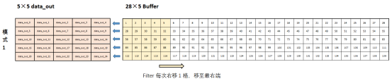
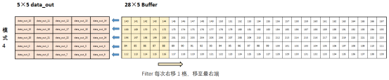
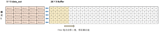
-valid_out_bufis always 0, and the Calc module does not work. Then-valid_out_bufbecomes 1, move the 5×5 filter in the buffer in the order from left to right, and determine the output valuedata_out_#. If the right end of the filter crosses the buffer, that is, it enters the invalid area, and assignsvalid_out_bufto 0 . If filter is moved to the far right, it will be moved to the far left again,valid_out_bufbecomes 1 again, and the Calc module starts working again. Filter moves from left to right and repeats the above process. During this process, the size of the buffer is fixed at 140. After loading the first 140 pieces of data, the data is updated one clock, and from the 141st piece of data, it enters the index 0, 1, 2... Overwrite the original data in it. Therefore, a separate mode setting is required, and the corresponding relationship between data_out and the data in the Buffer is changed after every fixed clock cycle.The distribution of output values in each mode is shown below:


-
conv1_calc:
valid_in:Enable signal, connected to valid_out_buf in Buffer module.
data_in_#:The 25 'data_out_#' output by the Buffer module each time.
conv_out_#:After the convolution operation is performed, the convolution output obtained by adding the bias value to the result value. The size of the filter is (5, 5, 3), so there are 3 channels and therefore 3 corresponding output ports.
valid_out_calc:Connect directly to the 'valid_out_buf' of the Buffer layer as the output.Use the system command $readmemh to read the weights and biases text file and store them in a two-dimensional array. The 25 data output by the Buffer layer in each round is used as the input of the convolution calculation, and the convolution operation is performed with the weight value, and then the bias is added to obtain the output. Although the handwritten digit image is a black and white picture and only needs a single channel, in order to not lose generality and improve accuracy, we still uses three channels to convolve it, so three sets of different weights and convolutions are used for 25 sets of data separately, and three sets of convolution operation outputs are obtained.
Pooling Layer 1 (Maxpool_relu)
valid_in: Connected to the valid output signal of the previous convolutional layer, the module performs two different operations according to the value of valid_in.
conv_out_#: Take the 3 12-bit convolution outputs of the previous convolutional layer as input data.
max_value_#: For each maximum pooling operation, the maximum value is selected from a range of (2, 2) in the feature map, and the final output is obtained after passing it through the ReLU function. Because there are 3 channels, there are 3 outputs.
valid_out_relu: Connect to valid_in of Buffer in convolutional layer 2, as a control signal to control the operation of Buffer in convolutional layer 2.
Since the filter size is (2, 2), a pooling operation will compare a total of 2×2=4 input data values. Perform segmentation operation according to the two control signals of state and flag, first compare the two data in the first line in (2, 2), and load the larger value into the buffer; then put the second line in (2, 2) A number is compared with the value in the buffer, and the larger value is loaded into the buffer; finally, the last number in (2, 2) is compared with the value in the buffer, and the corresponding operation of ReLU is performed on the larger one, that is If it is a positive value, it will not change, if it is a negative value, let it be 0. Each time a 3-channel 2×2 pooling operation is performed, the output valid_out_relu is 1, and the pooling layer 1 performs a total of 12 3-channel 2×2 pooling operations.
Convolutional Layer 2
conv2_buf & conv2_calc share the similar structure with those in Convolutional Layer 1. The only difference is that the input and output size changes and the operation changes to a 3-channel one.
Pooling Layer 2 (Maxpool_relu)
The module structure is also nealy the same as that of pooling layer 1. The only difference is that values of the three module parameters of HALF_WIDTH, HALF_HEIGHT, and HALF_WIDTH_BIT are changed from 12, 12, and 4 to 4, 4, and 3.
Fully Connected Layer (fully_connected)
valid_in: It is connected to the valid output signal of the pooling layer 2, and then connected to the enable signal of the last comparison module. When it is 1, it can control the comparison module to load data.
data_in_#: The maximum value obtained in the range of (2, 2) in the pooling layer 2 each time, after the ReLU function, the sign bit is expanded as the input data of the fully connected layer.
data_out: The input 48 data, the output value obtained by performing the convolution operation using the weight value and the bias value. Through 10 sets of different weights and biases, 10 sets of different outputs can be obtained, which are used as input into the final Comparison Layer.
valid_out_fc: Every time you get a -data_out output, this signal goes to 1 to enable the compare layer to load this output data.
Since the output feature size of pooling layer 2 is (4, 4, 3), a buffer of size 4×4×3=48 needs to be set to store the input data, and 3 data are loaded per clock. In the first 16 clock cycles, waiting for the data to be loaded, valid_out_fc remains 0 unchanged. When the loading is completed, the first data_out output can be obtained, so at the same time, make valid_out_fc become 1, enable the comparison layer, and let the comparison layer load the first output data. In each clock cycle after that, first let valid_out_fc return to 0 to prevent the comparison layer from repeatedly loading the last output value before calculating the new output. When a new data_out output has been calculated and generated within this clock, valid_out_fc is again set to 1 and the compare layer is loaded with this data. After 9 cycles, all 10 output data are generated and loaded into the last comparison layer, and the comparison layer performs comparison operations on them.
Comparison and Output Layer(comparator)
valid_in: Connected to the valid_out_fc output signal of the fully connected layer. When it is 1, the output data of the fully connected layer is loaded.
data_in: Connect to the data_out of the fully connected layer, and load 10 different data_outs of the fully connected layer in sequence within 10 clock cycles.
decision: The identification result by CNN's learning process of the input data, the result is a number between 0 and 9.
valid_out: The output signal that a complete classification operation is completed.