This page deals with the main-task (Taskboard). To see the report of the BYOD-report, click here.
The setup consists of
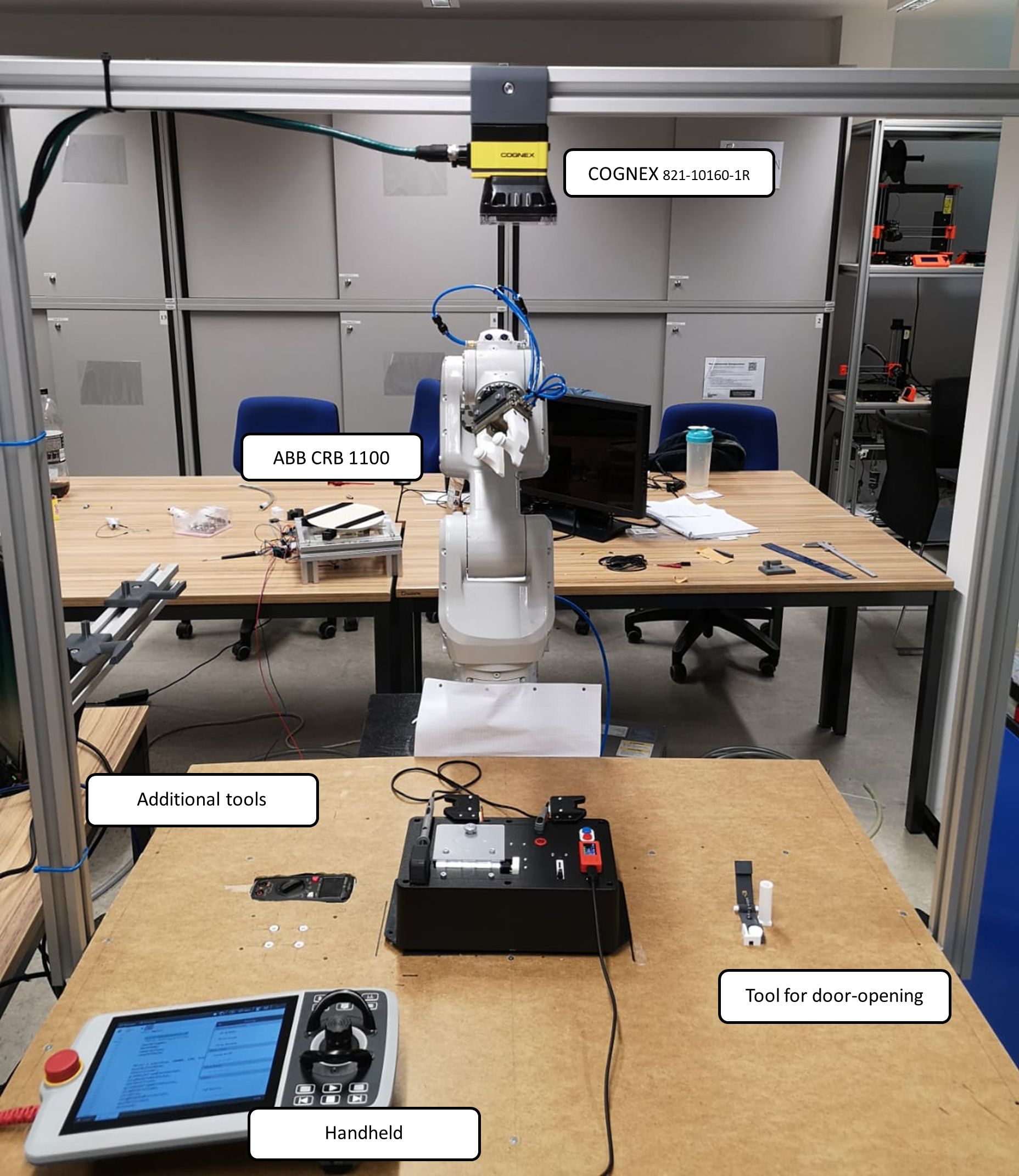
- Base (Table consists of aluminum profiles)
- ABB CRB 1100 + OmnicorC30 control unit
- Schunk parallel gripper (MPC 075) with 3d printed plates
- COGNEX 821-10160-1R camera
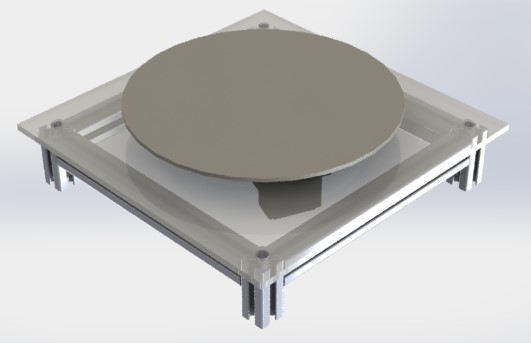
- (optional) turntable as additional axis (self-crafted)
- additional tools in order to fullfill the tasks
constraints, or see below
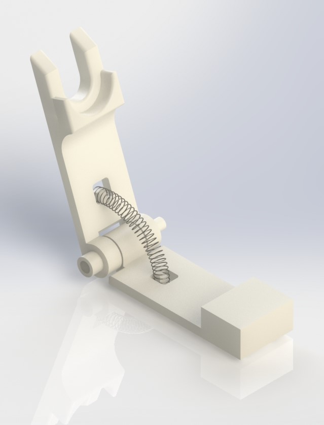
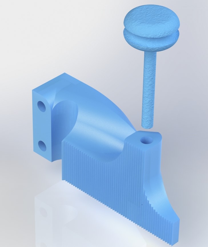
To overcome this limitation, we decided to create tools, such as a gear-spring mechanism to open the door, and an additional axis to rotate the whole taskboard to a suitable orientation. The additional axis is controlled by the robot control system and does not require any human interaction. While there are specific orientations of the taskboard in which the additional tools are not necessary, we wanted to ensure that our robot could adapt to any random orientation of the taskboard. However, at the time of submission the integration of the turntable to the robot system does not work with a sufficient reliability. Thus, we did not use it in our final submission video. Nevertheless we made a great effort in the developing process, which is why we still want to present it in our report.
Despite the tools we presented, the gripping mechanism itself was the most crucial part of our design. To perform all of the requested tasks efficiently, we needed to create a gripper plate that was significantly different from any existing types on the market. Our solution, especially for the wire-winding task, was to incorporate pulleys into the plates. These pulleys, when in a closed configuration, created a small gap for the wire, allowing it to be held tightly while still maintaining the necessary freedom of motion to wind the wire.
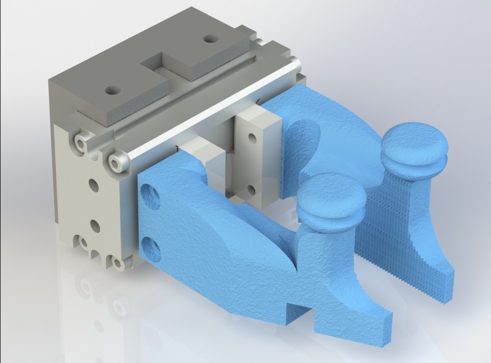
Why do we use such a complex construction for the wire-gripper part?:
The reason why we decided to use pulleys is that from our point of view it is the method which damages the wire least. Other options - like simply grabbing it or using a bigger gap which allows some motion - would still evoke very high friction and would destroy the wire over time. With our solution, friction is neglectable and as a matter of fact the service life of the wires increases.
Our approach was to split all of the sub-tasks into separate methods to make them independent of any given sequence. However, there is an initialization sequence that was provided by the task.
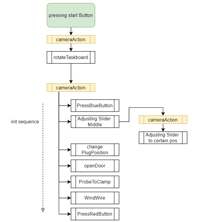
In the flowchart above, you can see that the process 'camera action' is repeated three times. This indicates that a specific camera job is loaded onto the camera, executed, and the results are received. More information about the camera (vision) jobs will be provided in the next paragraphs.
We used the Cognex Vision framework in order to locate the taskboard and its orientation. In detail, we generated several different "jobs", which got called by ABB's rapid-code. Specifically, we used the Cognex PatMax RedLine Pattern algorithm.- "newTaskboard.job" -> result: position and orientation of the taskboard
- "TaskboardOnTable.job" ->result: position and orientation of the taskboard
- "BYOD.job" ->result: position and orientation of the BYOD
In simple terms, the Cognex software generates an additional coordinate system that refers to the origin of the calibration coordinate system. To use the coordinate system of the taskboard, the object frame is copied from the camera target to a coordinate system that is available in ABB's RobotStudio IDE.
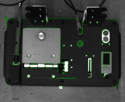
The origin of the taskboard coordinate system is set to the upper left corner (indicated by the green symbol), and all other positions are "hardcoded" with respect to this point.
Seperated from the localisation of the taskboard, there is another camera job to execute- "SliderDisplay.job" ->result: distance beetween green and yellow triangle
In order to detect the triangles, we used what are called 'blobs.' Blobs are a collection of several pixels with a common brightness. Since the blue screen of the display has a different brightness and number of pixels than the triangles, it is possible to separate them.
Since the orientation and position are already known by the system, the only important information is the distance between the triangles. Unfortunately, there are several edge cases that need to be considered:
| Case | definition | Image | sequence |
|---|---|---|---|
| regular | camera can distinguish between both triangles and reed the distance beetween them correctly | 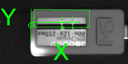 |
robot moves slider to determined position |
| overlap | triangles overlap. So the blob algorythm can´t find 2 seperate triangles, since they merged to one big collection of pixels | 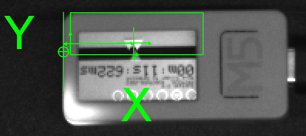 |
robot moves slider 5mm from middle postion in both directions. This sequence is indicated by a short blue blink of the robot´s built-in lamp |
| done | A rare case, in which the triangles overlap so tight, that the task is already done by simply moving to the middle triangle. | 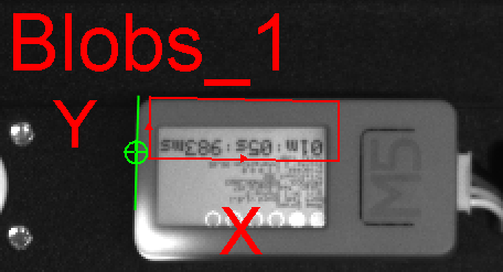 |
should be none. To avoid errors due to false interpretation, we decided to start the same sequence like in "overlap". |
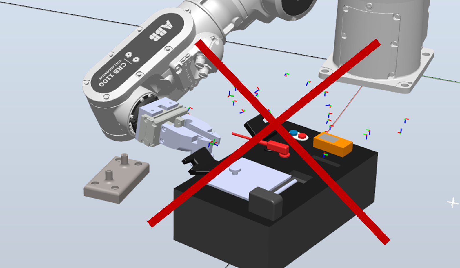
Another aspect to consider is that the taskboard must maintain a minimum distance from the robot's base. If this minimum is undercut, the robot's joints would collide, and the robot would stop. While holding this minimum distance, it is nearly impossible to open the door by simply grabbing the knob and performing a circular movement that is out of the robot's reach. Hence, opening the door and winding the wire would be mutually exclusive. Therefore, we created the 'door-opener' tool, which bypasses the problem of limited range. With this tool, we are now able to open the door from the front side.
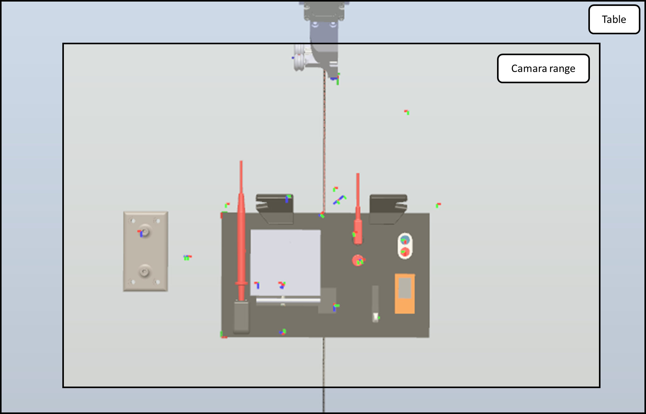
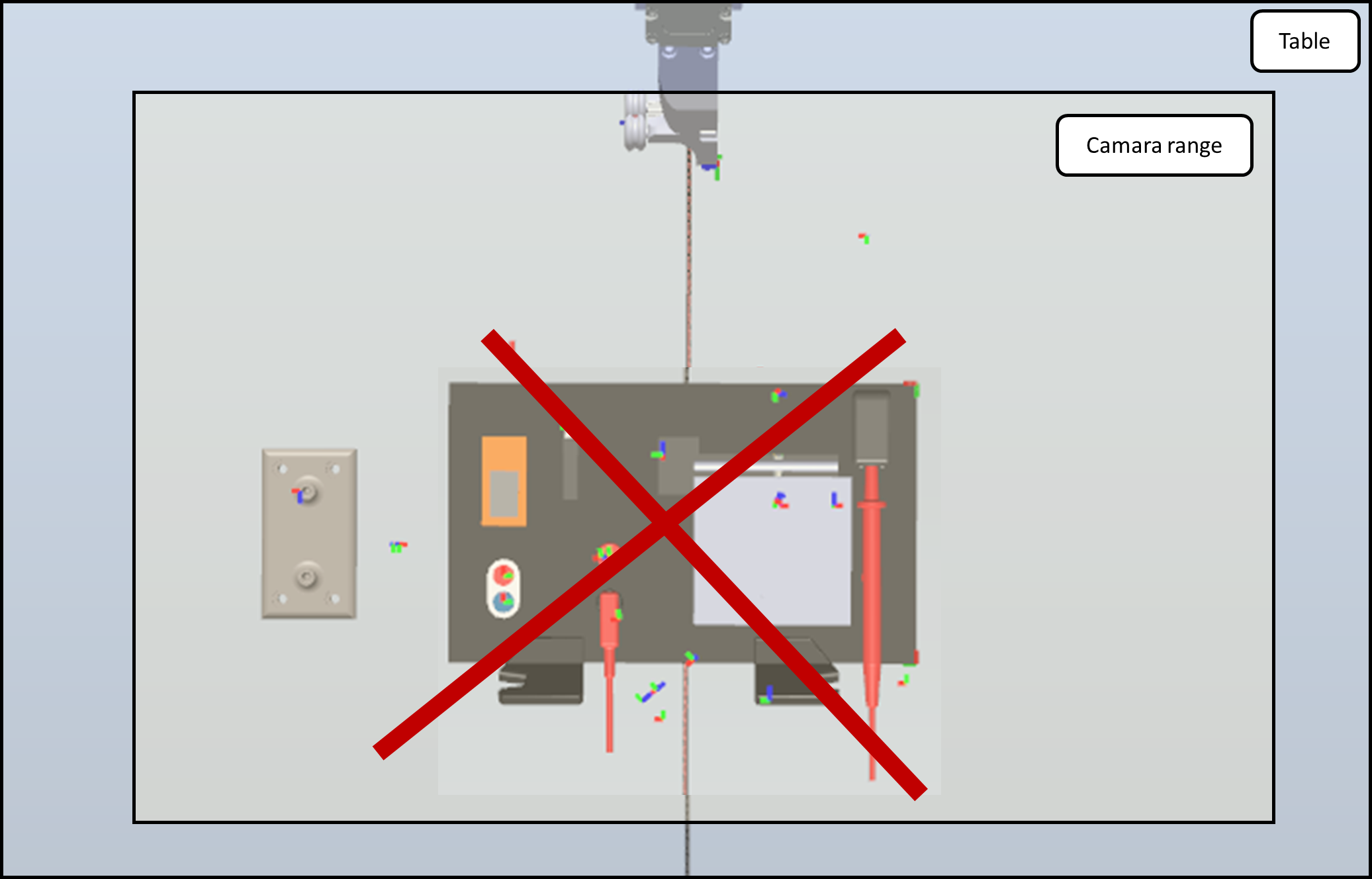
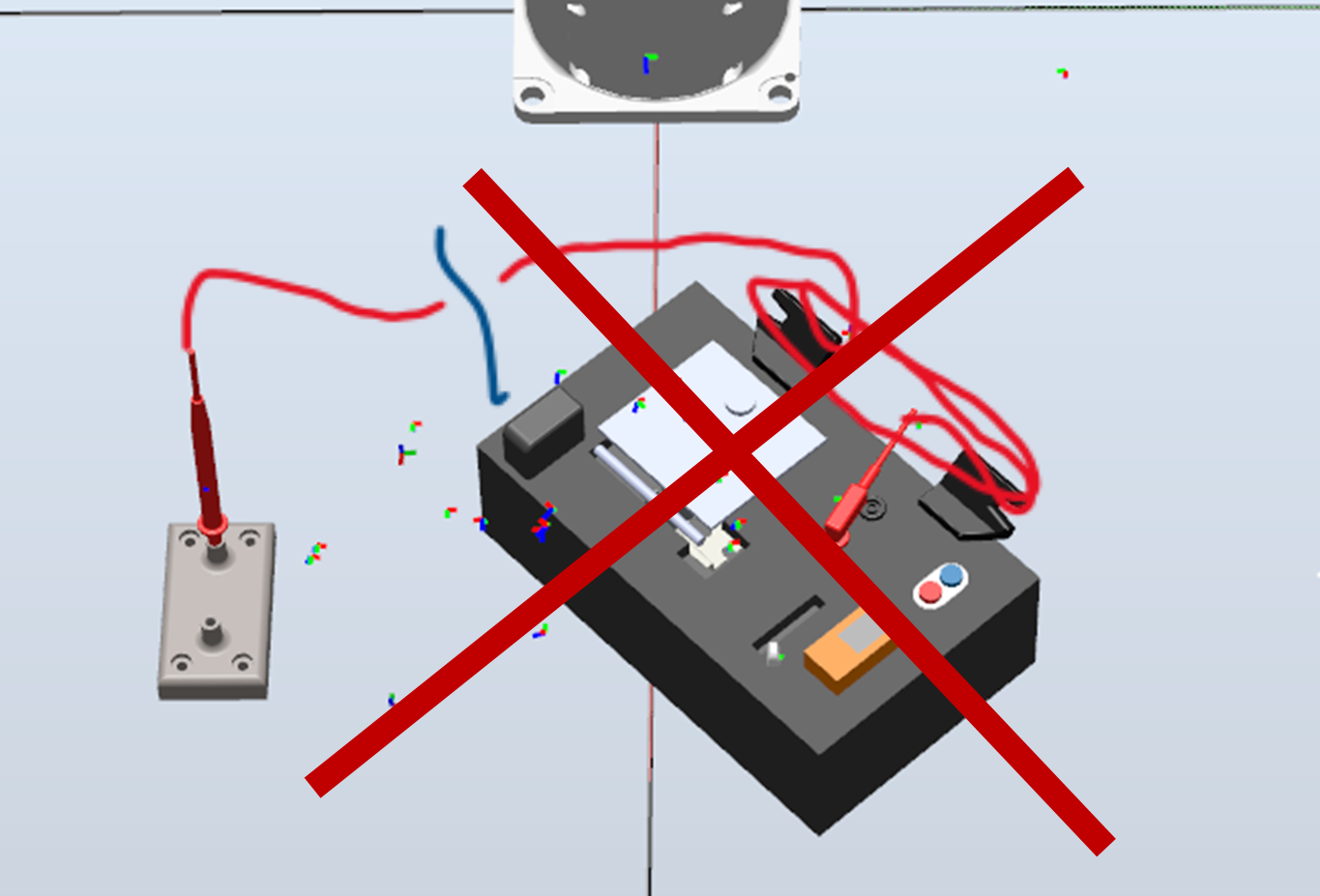
Due to the fact that we only use one robot, the combination of the winding task and the probe itself cause another constraint. After pluging the probe into the regular clamp, we can not plug it back to the white socket because it would interfere with the winding task. So we have to plug it to an temporarily clamp which allows us to taking it back from a determained position after the winding task. Since we must wind the wire 2 times to guarantee an "always-working solution", the rest of the wire becomes very short. That is the reason why we were forced to reduce the accepted orientation-angle to about -10° (left image) to 45° (right image). To clarify: orienting the long side of the taskboard parallel to the robot´s base would lead to an angle of 0°. Angle is counted positive counter-clockwise.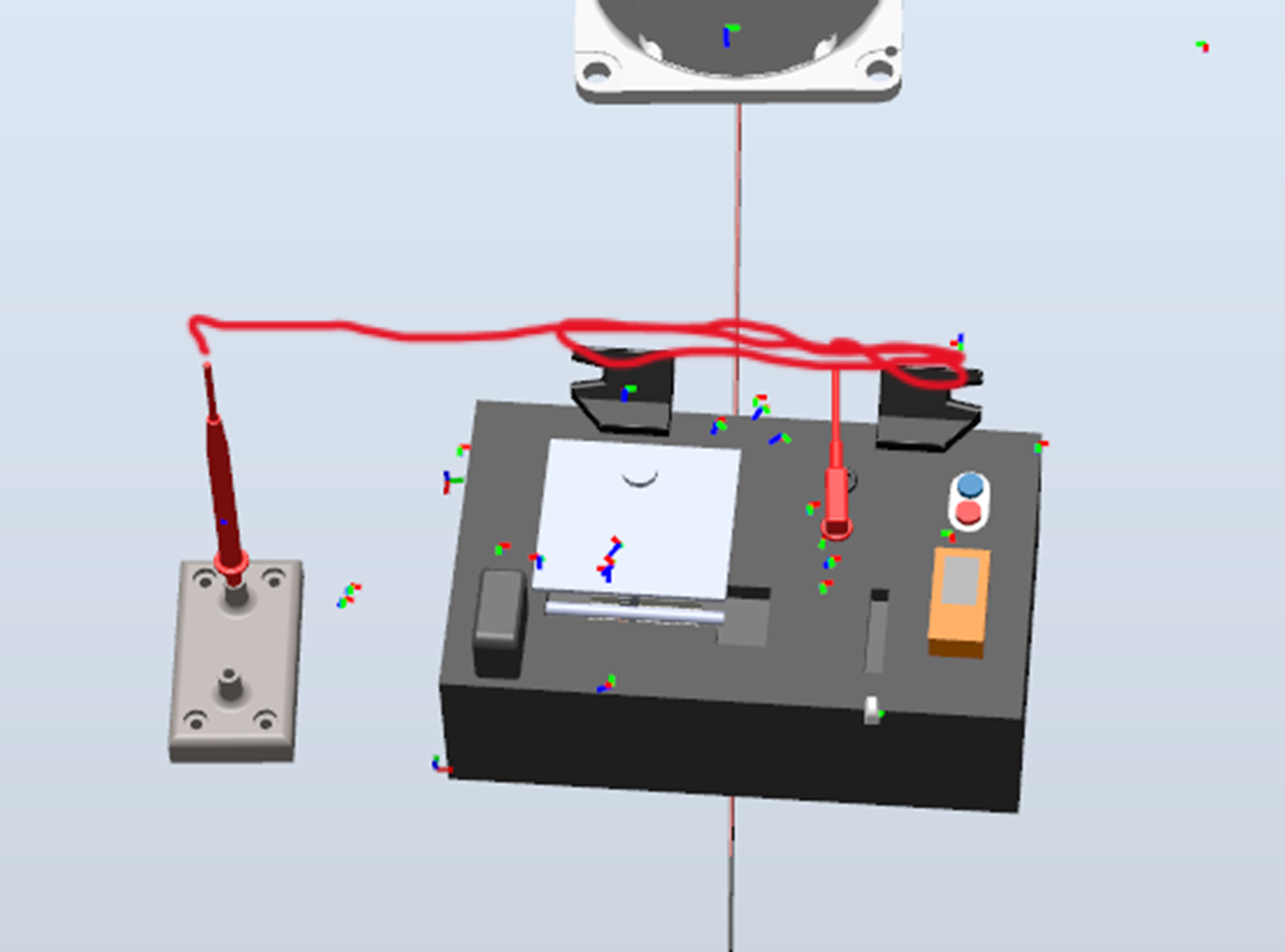
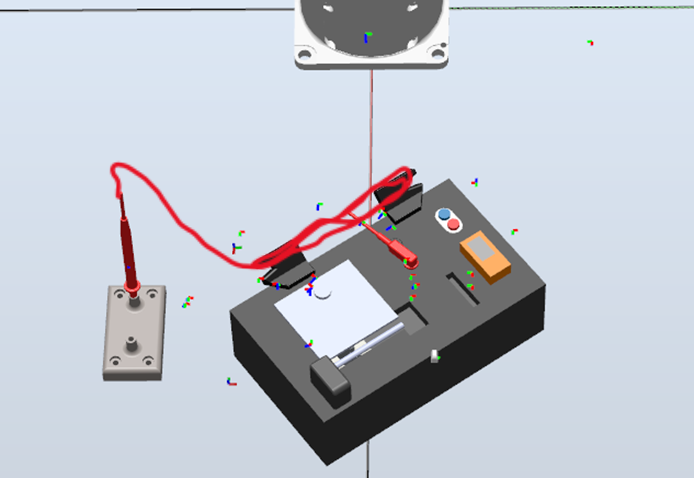
If we fall below the bottom limit (left image), the wire will be too short and would tear the probe from the temporarily clamp. If we exceed the the angle in positiv direction (right image), the winding task won`t work due to the limited range of motion of the robot.
- if the task seems to be impossible: be creative and create a tool to solve it
- first things first: Set up the working station perfectly at the beginning, not in the end. (we had to learn it the hard way)
- mount camera seperatly from the robot. If robot moves fast, the camera wiggles a bit
- wires are hard to control and their behaviour is nearly unpredictable
- wire´s behaviour change tremendously after changing the velocity of the robot
- clean up your working station before using the robot -> it will definitely reduce damages
- treat any suggestion for a solution instead of ruling it out instantly
To run the software solution, follow this sequence:
- Print all .step files with a 3d printer (slice to gcode)
- Mount gripper
- Install ABB Robot Studio or run directly from FlexPendant via USB
- Import the software solution
- Connect the camera to the controller via Profinet
- Select camera IP adress in the IDE
- Store all .job files on the camera
- change light level to fit to the environment
- calibrate the camera via cognex grid
- calibrate robots workobject coordinate system to the grid
- run the solution via ABBs IDE in hand-operation-mode and check if all trajectories are suitable
- change robots settings to automatic mode in order to operate with full speed
- ABB robot studio IDE, usage of software package Rapid
- Cognex Vision framework
- Arduino IDE + stepper.h library (stepper motor for turntable)
Sebastian Neuhofer, Christian Scheidl, David Seyser, Julian Smole