Manual for the N2 cooling system
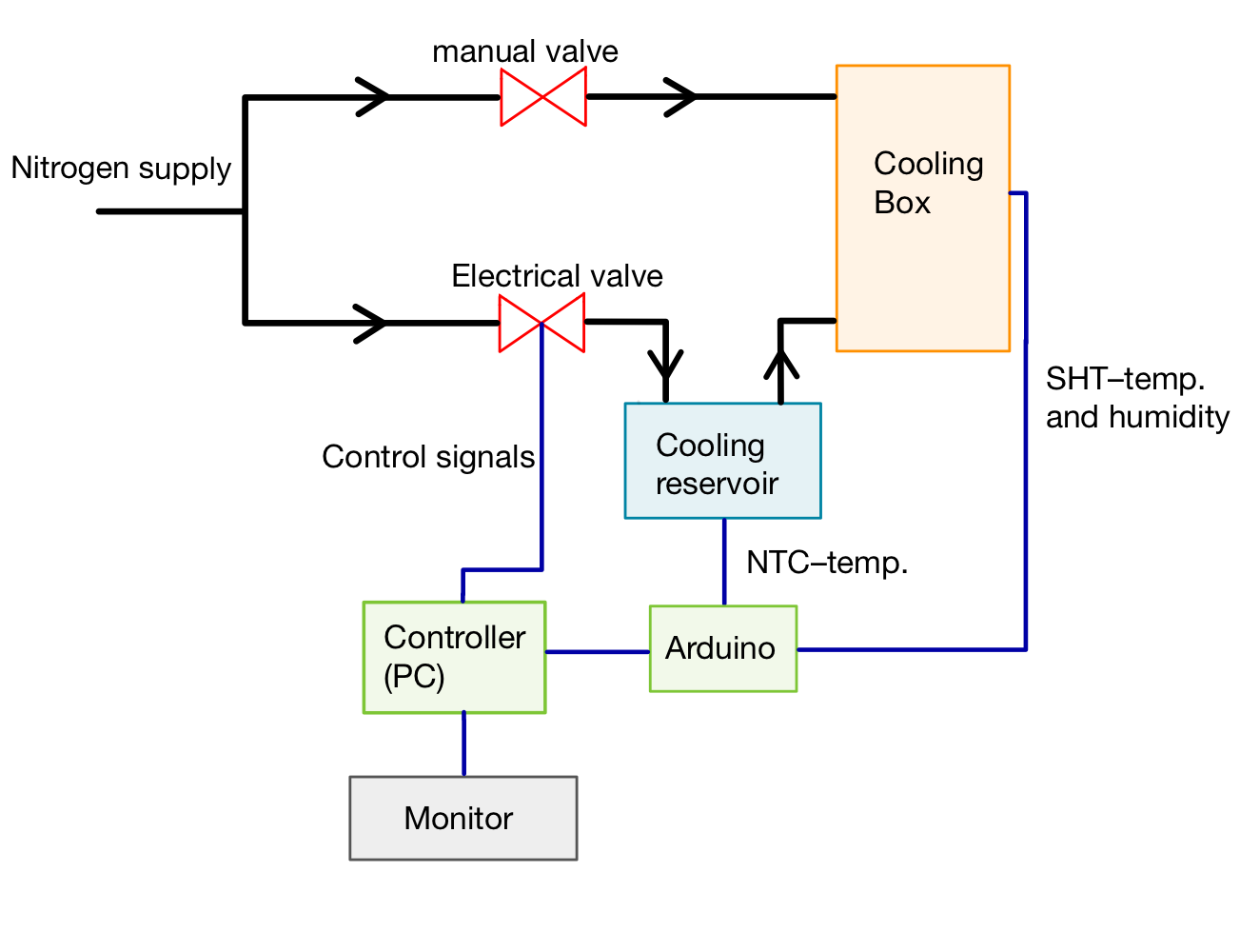
The cooling system is used at test beam measurements to cool down the DUT. The system uses two nitrogen lines. One line is used to supply the cold nitrogen into the cooling box which contains the DUT. It goes through a cooling reservoir which is filled with dry ice while the cold nitrogen is regulated by an electrical valve. The other nitrogen line supplies warm nitrogen and is controlled by a manual valve. This line is only used in the end to heat the box up safely.
The temperature and humidity of the cooling box and the temperature of the cooling reservoir is measured and processed by an Arduino. The data is then send to the PC where a python program generates a control signal from it. This control signal is send to the electrical valve which regulates the nitrogen flow.
The current temperature and humidity in the DUT box as well as the temperature of the dry ice supply is monitored, logged to a file and published via a socket to view it using the online_monitor package.
In the beginning the cooling setup has to be assembled. There are four main components that have to be connected through the following steps:
-
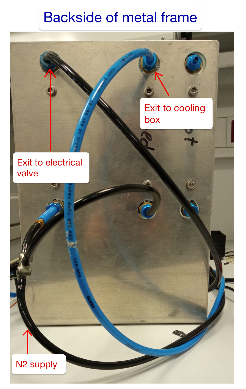
Connect the nitrogen supply to the metal frame with the manual valves by using the tubes. Choose the connection type according to the supply you are using. The supply should provide nitrogen for the 50 LPM and for one of the 10 LPM valves by using a T-piece.
-
Connect the 50 LPM valve to the electrical valve while the 10 LPM valve goes straight up to the cooling Box. It will be used for drying and heating up the DUT. Do not connect it to the gas distributor in the cooling box! This one is reserved for the cold nitrogen. Use the cable entry for the connection.
-
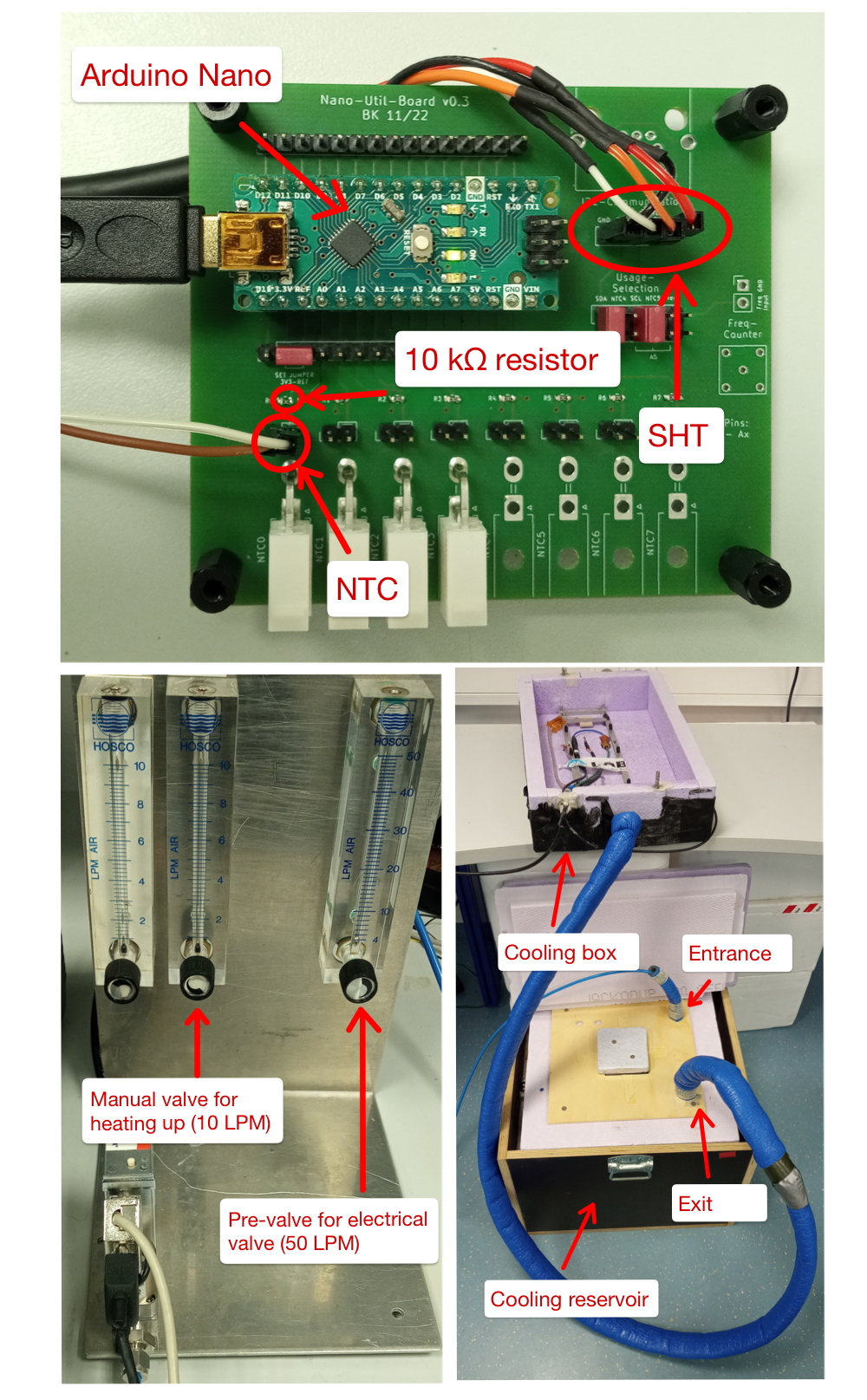
Connect the electrical valve to the entrance of the cooling reservoir (ice box). The entrance is the tube without the insulation coating.
-
Connect the exit of the cooling reservoir (tube with insulation coating) to the gas distributor. Use the main entrance to the cooling box.
-
Take the PCB which is used for the cooling and plug in the SHT- and NTC-sensor (it is possible to use the molex plugs for the NTC sensor). Your Arduino nano has to be flashed with the firmware.
-
Power the electrical valve with 15Vdc
-
Connect the Arduino and the electical valve to your PC via USB. Make sure that the Arduino uses port 0 and the electrical valve port 1. If this is not possible you can change the used USB ports in cooling.py.
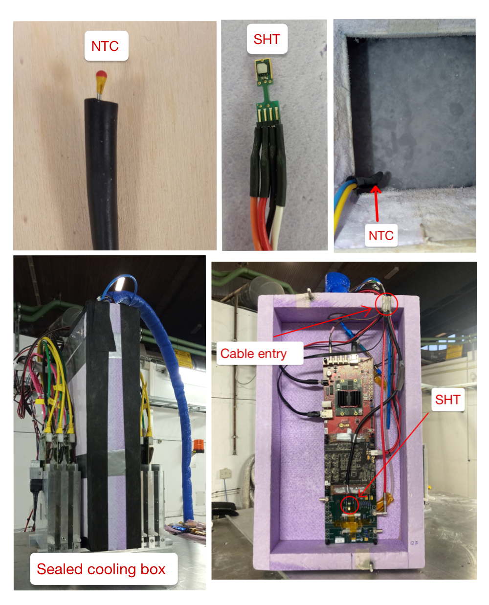
Before sealing the cooling box you have to mount your DUT on the frame inside. The SHT sensor should be fixed next to it in a position where the nitrogen can circulate. To observe the temperature in the cooling reservoir the NTC sensor has to be hanged over the ice layer. Usually 8-10 hands full of dry ice last up to 10 hours.
Now it is important to seal the cooling box properly. For closing the cable entry you can use Bostik gum. It is recommended to wrap a little piece of gum around every cable before stacking them in the cable entry. Remaining gaps can be sealed with more gum. To close gaps at the lid use gas tight tape and wrap it around the box. On the one hand a good insulation is necessary to reduce the heating due to the entering of warm air. On the other hand you do not want to seal it too much so the nitrogen can escape after being heated up by the DUT.
For the software installation start by cloning the git repository with git clone https://github.com/SiLab-Bonn/n2_cooling.git. Make sure that you have installed the packages in the requirements.txt via pip install -e .. To set up the online-monitor go to the online-monitor file where the converter and receiver is and use plugin_online_monitor. You can also use plugin_online_monitor n2_cooling/online_monitor if you are in the cloned git folder. Next you have to flash the Arduino nano with the firmware. For that you can use the Arduino IDE. Make sure that you have installed the library arduino-sht. Use the library manager for that. After the firmware is flashed successfully and the packages are installed, you can start with the cooling.
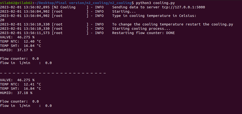
After the software is installed properly you can start the online monitor with start_online_monitor online_monitor.yaml to have the cooling process visualized. Make sure that the 10 LPM valve ist closed and the 50 LPM is opened. For starting the cooling use n2cooling. Then you will be asked about your desired target temperature. Put in the target temperature.The cooling should now reach the temperature automatically. If this does not work, try to seal the cooling box better or check the flowrate passing through the electrical valve (a maximum flowrate of 25 l/min is possible). In addition to the online monitor it you get a output of the cooling values in the terminal.
To restart the cooling or to type in a new target temperature you have to restart the programm.
you can stop the cooling by setting a high target temperature. You can also turn off the electrical valve or close the 50 LPM valve. To avoid short circuits you have to open the 10 LPM valve for drying the cooling box while the cooling stopped. This will also help to heat the DUT up faster.
When the cooling setup is used for a longer period it is possible to face problems with the temperature of the nitrogen. The reason for that is a insulating layer of ice that forms around the tubes inside the cooling reservoir. To solve this problem you have to stab into the ice and mix it. In addition you could get rid of the old ice when you are refilling the box.
To have a better measurement of the real temperature of the cooling reservoir the NTC sensor can be placed under the ice near the tube where the nitrogen is cooled in.