At WRO Open 2025 in Slovenia, things started off really well for us. In the Open Round Challenge we managed to get full points in just 24 seconds, the fastest time there. Before that, in practice, the robot was running smoothly through all the tests and random cases we tried. At some point it had some strange speed drops, which we thought were from a bad cable connection. We resoldered everything, and from then on it worked perfectly again. Then came the real chaos. Just five minutes before the first official Obstacle Round, our motor driver chip blew up with a small spark. We tried to swap it out, but there just wasn’t enough time. The result: 0 points. Not exactly how we imagined the round going. That afternoon we stayed and worked on the robot, replacing the broken chip and all the resistors and capacitors around it. The next day, during the two hours of practice, the robot was back on track and almost hit full points again, but with small inconsistencies on the parking alignment. In the official run though, it made a small drift when doing the parking, and touched the parking wall, and because of the rules the whole parking didn’t count—not even partially. That was a bit painful, but in the end we still took 2nd place overall, and on documentation we scored 28 points. So yeah, it was a mix of highs and lows: fastest run of the round, a blown motor driver, afternoon repairs, and a nearly perfect comeback.
Thanks to HyperLine Robotics for sponsoring us!
Repository of Nerdvana Taurus Team competing in the World Robot Olympiad (WRO) 2025, Future Engineers category.
- 👥 The Team
- 🎯 Challenge Overview
- 🤖 Our Robot
- ⚙️ Mobility Management
- 🛠️ Power and Sense Management
- 💻 Components coding
- 📝 Obstacle Management
- 📽️ Performance Video
- 💰 Cost Analysis
- 📂 Resources
- 📜 License
This repository is organized as follows:
📦 WRO2025_Future_Engineers
├── 📁 3D-models             # Contains 3D design files for the robot's components
│   ├── 📁 old-3D-models     # Previous versions of 3D models
│   └── 📁 step-models       # 3D models in STEP format
├── 📁 electrical-schematics # Circuit diagrams and wiring
├── 📁 github-commits        # Commit logs and change tracking details for this repository
├── 📁 media                 # Images and videos
│   ├── 📁 robot-photos      # Photos of the robot
│   ├── 📁 team-photos       # Pictures of team members and teamwork
│   └── 📁 video             # Recorded testing
├── 📁 other                 # Contains files that do not fit into other categories
├── 📁 src                   # Main source code for the robot
├── 📁 technical-draws       # Technical drawings and mechanical blueprints
├── 📁 video                 # Videos of our robot
├── 📄 LICENSE               # MIT License for the project
└── 📄 README.md             # Main documentation for the project

*This image was taken at the WRO 2023 International Final in Panama, where we placed 14th in the Robomission Junior Category.
Age: 17
High School: International Computer High School Bucharest (ICHB)
Description:
Hi! I’m Andrei from Romania, and this is my fifth WRO season. This is my first season in Future Engineers, as before I competed in Robomission category. I am passionate about robotics especially electronics and latest algorithms and tech. Over the years, I have worked on multiple robotics projects, including line followers, sumo bots, and air quality modules. Apart from robotics, I also enjoy cybersecurity, programming, and cycling.
Age: 16
High School: National College "Mihai Viteazul" (CNMV)
Description:
Hi! I’m Horia from Romania, and this is my second WRO season competing alongside Andrei. I have participated in RoboMission multiple times, gaining valuable experience in solving various problems that may arise while building a robot. I have a strong interest in technology and robotics and am always eager to learn and experiment with new ideas.
The WRO 2025 Future Engineers challenge pushes teams to develop a fully autonomous vehicle capable of navigating a dynamic and randomized racetrack using sensors, computer vision, and advanced control algorithms. The goal is to complete multiple laps while adapting to randomized obstacles, following strict driving rules, and successfully executing a parallel parking maneuver at the end of the course.
-
🏁 Open Challenge: The vehicle must complete three (3) laps on a track with randomly placed inside walls.
-
🚦 Obstacle Challenge: The vehicle must complete three (3) laps while detecting and responding to randomly placed red and green traffic signs:
- 🟥 Red markers ➜ The vehicle must stay on the right side of the lane.
- 🟩 Green markers ➜ The vehicle must stay on the left side of the lane.
After completing the three laps, the vehicle must locate the designated parking zone and perform a precise parallel parking maneuver within a limited space, adding an extra layer of difficulty.
-
📑 Documentation: Each team must maintain a public GitHub repository showcasing their engineering process, vehicle design, and source code.
Scoring is based on accuracy, technical documentation and speed, rewarding teams that balance efficiency, adaptability, and innovation. This challenge not only tests robotics and programming skills but also promotes problem-solving, teamwork, and engineering creativity.
🔗 Find out more about the challenge here. 🚀
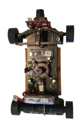 |
 |
|---|---|
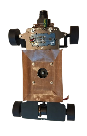
Top |
Bottom |
 |
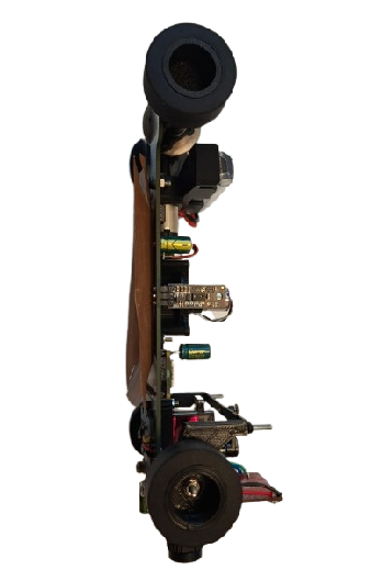 |
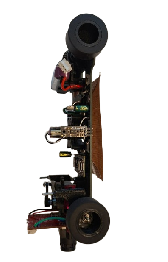
|---|---|
Left |
Right |
 |
 |
|---|---|
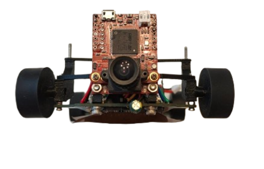
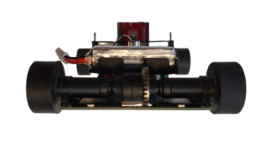
Front |
Back |
The robot's mobility is controlled through a fully PCB chassis, a servo-based steering system, and a drivetrain featuring a RC differential and axes. These components work together to ensure smooth, precise movement with optimized traction, stability, and efficient power management.
The drivetrain uses a sealed RC differential at the rear, driven by a Pololu 30:1 HPCB micro gearmotor through a 3D printed pinion → differential input gear. The motor is held in a 3D-printed support with the battery mounted above, keeping the center of mass centered and low. Rear outputs rotate in bearings seated inside 4 printed rings that are super-glued to the PCB chassis, minimizing friction and parts count. At the front, the wheels are fully 3D-printed and each wheel runs on two bearings (inner + outer) for a rigid, wobble-free hub that steers precisely.


To maximize grip on the track without adding mass, we use a downforce impeller (1020 coreless motor) that pulls air from under the robot, increasing the normal force. The impeller is PWM-controlled via an RFR3411 MOSFET (low-side switch). The drive motor is controlled by an IFX9201SG driver (PWM + DIR) with an active brake pulse for precise stopping, while the encoder on the gearmotor provides odometry for short, accurate moves (e.g., avoidance hops, parking nudges).
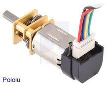
Following past testing, we selected a high-power 30:1 Micro Metal Gearmotor (12V) for the drive system. This motor provides an optimal balance of speed and torque, allowing the robot to maintain stability while navigating turns.
 |
Specifications |
|---|---|
| Model: 30:1 HPCB | Voltage: 6V |
| No-load Speed: 1000 RPM | No-load Current: 120mA |
| Stall Torque: ~0.4 kg·cm | Stall Current: 1.6A |
| 🔗 Buy Here | Function: Drives the robot |
Why We Chose This Motor?
- Gear ratio provides suffi cient torque without sacrificing efficiency.
- Compact and lightweight design, allowing integration into a lightweight robot.
Our robot uses cast silicone tires on 3D-printed hubs. Silicone provides high, repeatable static friction on painted boards and vinyl, which pairs perfectly with the rear differential and downforce impeller—more grip when we need it, without adding mass.
Why silicone?
- Grip & consistency: Strong adhesion on smooth surfaces → faster exits and shorter braking distances.
- Low wear on the map: Softer compound grips without scratching.
- Stable handling: Predictable breakaway, so PD/PID steering stays smooth.
Construction:
- Rims: 3D-printed hubs with dual bearings (inner + outer) for a rigid, wobble-free wheel.
- Tire: Cast silicone ring fitted onto a mechanical bead on the rim (no harsh solvents needed).
- Fit: Rear wheels mount directly to the diff outputs; fronts ride on steering hubs for low friction.


The IFX9201SG motor driver is used to control the robot’s high-performance drive or impeller motor with precision and efficiency. It supports PWM-based speed control and direction control while integrating advanced protection features, making it ideal for demanding robotics applications. The IFX9201SG is directly integrated into our PCB, ensuring compact design and reliable communication with the Arduino Nano ESP32.
 |
Specifications |
|---|---|
| Model: IFX9201SG | Operating Voltage: 5.5V – 45V |
| Logic Voltage: 3.3V / 5V compatible | PWM Frequency: Up to 20 kHz |
| Max Continuous Current: 5A | Max Peak Current: 8A per channel |
| Control Interface: PWM + Direction pins | Built-in Protections: Overtemperature, Overcurrent, Undervoltage, Short-to-GND/Battery |
| 🔗 Buy Here | Function: Controls drive motors |
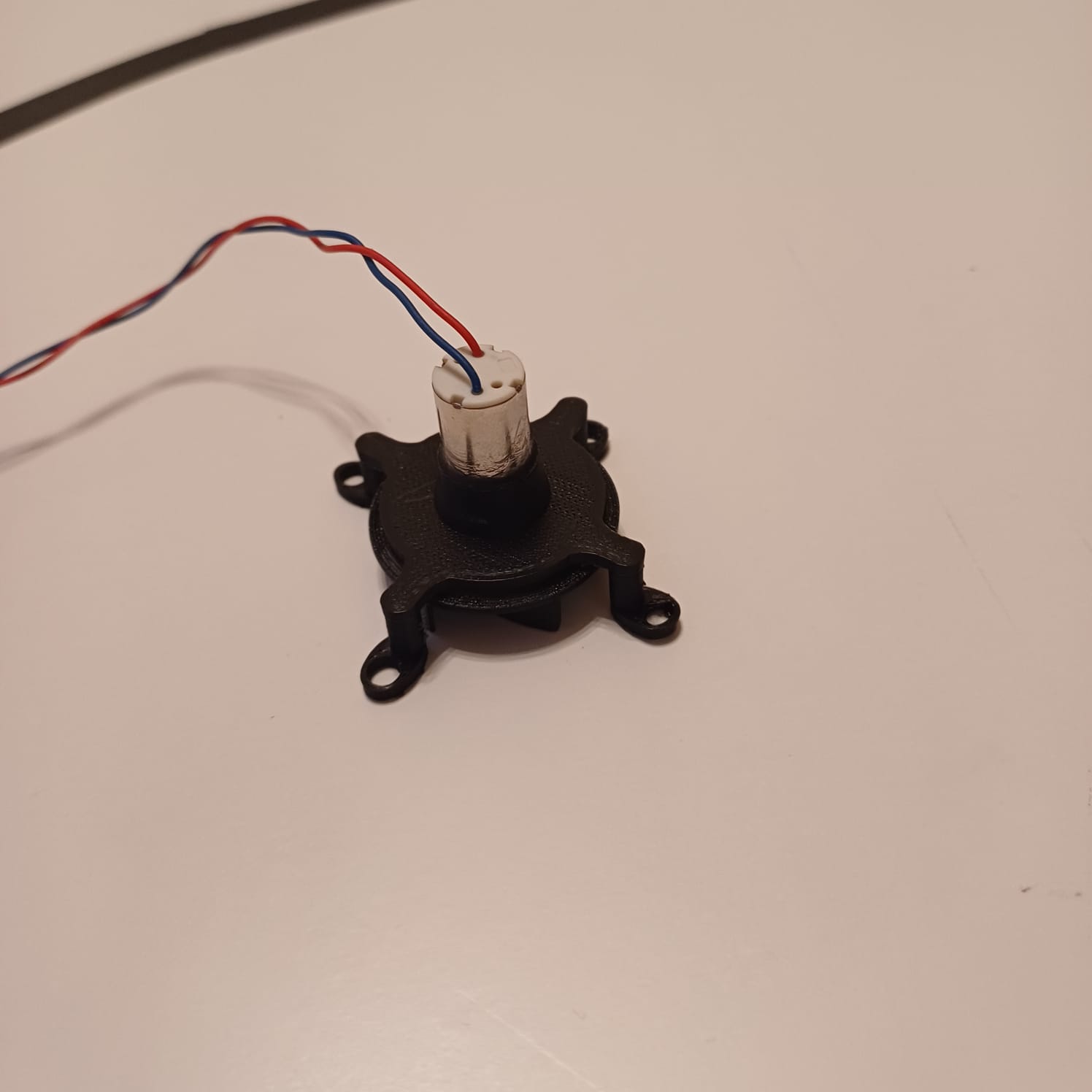
The impeller generates downforce to improve the robot’s grip on the track at high speeds. Powered by a 1020 coreless DC motor, it delivers extremely high RPM with minimal weight, making it ideal for competitive line follower and robotracer builds. Its low rotor inertia ensures instant acceleration, while the compact size allows for easy integration.
 |
Specifications |
|---|---|
| Type: Coreless DC Motor | Model: 1020 |
| Voltage: 3.7–7.4V | Shaft Diameter: 1.0mm |
| No-Load Speed: ~53,000 RPM @ 3.7V | ** Weight:** ~4.5g |
| Current Draw (Avg): ~1A @ 3.7V | Peak Current: ~2.5A |
| 🔗 Buy Here | Function: Drives the downforce impeller |

The steering system is a critical part of the robot, ensuring precise maneuverability and smooth turns. Our design is based on a parallelogram steering mechanism, where both front wheels turn at the same angle through a single servo-controlled linkage. This setup provides predictable and stable steering, making it easy to use for an autonomous vehicle. Instead of using an Ackermann steering system, which requires more complex calculations and linkages, we opted for a simpler and more lightweight solution that offers consistent control. Our steering system allows for a maximum turning angle of 80 degrees in both the left and right directions. This range provides precise maneuverability, enabling the robot to navigate sharp turns efficiently while maintaining stability.

Our steering arm is directly connected to the servo, which moves the two front wheels simultaneously. This ensures that the turning response is immediate and proportional to the servo's motion. The wheels are mounted on special mounts hubs, allowing for smooth and precise movement without excessive friction. To ensure structural integrity and long-term reliability, the steering system is assembled using 2 M2 screws on which the hubs can turn.


⚙️ Design Considerations & Improvements
While the parallelogram steering system is effective, some potential enhancements could improve its performance. Additionally, optimizing the motor mounts could reduce mechanical play, making the system more precise. In future iterations, we may experiment with Ackermann geometry and suspension to better distribute wheel angles during turns, further improving efficiency and reducing tire slippage.
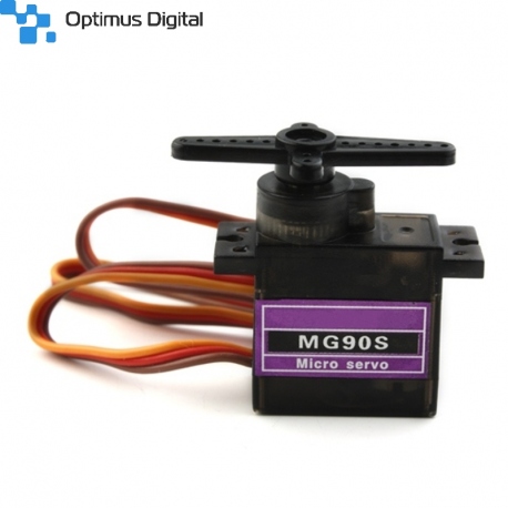
To control the steering system, we use an MG90S micro servo, known for its high torque and fast response. This servo enables quick and precise adjustments while maintaining a compact and lightweight design. Featuring metal gears, it ensures durability and reliability over extended use. The servo is securely mounted onto the chassis with two screws, and the steering arm is directly attached to its output shaft, providing smooth and efficient motion transfer for accurate steering.
 |
Specifications |
|---|---|
| Model: MG90S | Voltage: 5V |
| Torque: 2.2kg/cm | Signal Type: PWM |
| Current Draw (Avg): 120mA | Peak Current: 500mA |
| Weight: ~13.4g | Gears: Plastic |
| 🔗 Buy Here | Function: Controls steering |
At the national stage, we used a fully 3D-printed chassis, which allowed us to quickly prototype a compact and optimized structure. However, for the current version, we upgraded to a PCB-based chassis. This not only reduces weight further but also integrates electronics directly into the structure, making the robot lighter, cleaner, and more reliable.
The robot is driven by a single high-performance motor, which is connected to a professional RC differential. This setup allows reducing complexity while maintaining precise control over movement.

➜ Lightweight & Durable – The PCB chassis ensures a strong lightweight structure, optimizing performance.
➜ Balanced Design – The battery is centrally placed on top of the motor, ensuring even weight distribution and stability. Meanwhile we use a high power impeller that sucks the air under the robot and create an artificial downforce effect over the robot maintaining its grip.
➜ Easy Component Mounting – Pre-designed slots for motor, steering servo, and camera make assembly quick and efficient.
➜ Organized Wiring & Cable Management
🔹 Integrated PCB routing eliminates unnecessary wiring, ensuring a cleaner and more reliable setup.
🔹 Super glue secures servo and other tiny parts, keeping each part in its place even after longer runs.
🔗 Click here to watch the assembly video on YouTube
The 3D model files are available in the /3D-models folder. We used a BambuLab X1-Carbon, but any good quality printer will work.
Printed components include:
- Servo base – for securing the MG90S steering servo.
- Camera mount (90° bracket) – to hold the camera in position.
- Motor support – for fixing the drive motor with M3 screws.
- Bearing rings – 4 small rings to be glued on the PCB chassis for smooth differential rotation.
- Front wheels – fully 3D-printed, each equipped with 2 bearings (inner + outer) for stable and secured placement.
The final robot is built on a custom PCB chassis, manufactured by JLCPCB, which acts as both the structural base and the mainboard for electronics.
-
PCB Preparation
- Order the chassis PCB from JLCPCB.
- Solder the Arduino Nano ESP32 into its slot.
- Solder the 4 distance sensors with 90° male pins, positioned on all four sides of the robot.
-
Steering System
- Mount the MG90S servo on the 3D-printed base, then super glue the base securely to the PCB chassis.
- Fix the steering hubs (left & right) on M2 screws, allowing smooth wheel hub rotation.
- Connect the servo arm to the steering hubs using two metal link bars for precise steering.
- Install the 3D-printed front wheels, each fitted with dual bearings (inner + outer) for reliable and stable rotation.
-
Camera Mounting
- Attach the camera using the 90° 3D-printed bracket.
- Secure it with 2 screws to the chassis and 2 screws for the camera itself.
-
Motor & Drivetrain
- Place the drive motor on the 3D-printed support, fixed with 2 × M3 screws.
- Secure the impeller with 4 screws to its mounting position.
- Assemble the RC differential with the rear wheels mounts that directly fit the differential left and right mounting holes.
- Glue 4 printed rings on the PCB chassis to house bearings, ensuring smooth rear wheel rotation.
-
Wiring & Final Connections
- Solder all cables (servo, camera, motor encoder, impeller) to their designated pads on the PCB.
- Use minimal hot glue to fix loose wires and prevent interference during movement.
The robot's power and sensing system is designed for efficiency, precision, and adaptability. It consists of an Arduino Nano ESP32, a Li-Po battery, BMI088 IMU, OpenMV H7 Camera, motors(drive motor and servo motor), and a voltage regulator, all working together to ensure stable operation and accurate navigation.
Each component has been carefully selected to provide optimal performance, minimize power consumption, and ensure reliability in competition environments.
The Li-Po battery provides a compact, lightweight, and high-discharge power source, making it ideal for our robot. The 7.4V output is suitable for running our motors and voltage regulator, ensuring stable power delivery.
_1800x.jpeg?w=1000&h=1000) |
Specifications |
|---|---|
| Model: 2S Li-Po | Capacity: 300mAh |
| Voltage: 7.4V | Discharge Rate: 60C |
| Weight: 12g | Size: 13.8 x 12 x 52.5mm |
| Output Current: Varies by load | Connector Type: JST |
| 🔗 Buy Here | Function: Powers the entire robot |
The Arduino Nano ESP32 provides high-speed processing, built-in Wi-Fi and Bluetooth, and extensive GPIO capabilities in a compact form. This allows it to handle sensor data, motor control, and vision processing efficiently.
 |
Specifications |
|---|---|
| Microcontroller: ESP32 | Flash Memory: 4MB |
| SRAM: 520KB | Frequency: 240MHz |
| Pins: 22 | Input Voltage: 5V |
| Current Draw (Avg): 200mA | Peak Current: 500mA |
| 🔗 Buy Here | Function: Controls all robot components |
The BMI088 IMU is used to measure the robot's angular velocity and acceleration, helping it maintain stability and precise movement control. It is essential for calculating turns and avoiding drift.
 |
Specifications |
|---|---|
| Gyroscope Range: ±2000°/s | Accelerometer Range: ±24g |
| Interface: I2C / SPI | Supply Voltage: 3.0V – 3.6V |
| Current Draw: ~3.2mA | Weight: ~1g |
| 🔗 Buy Here | Function: Tracks orientation & motion |
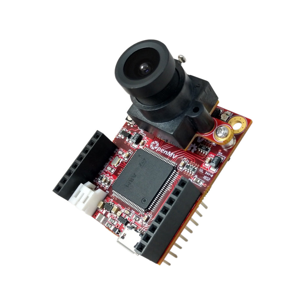
The OpenMV H7 Camera processes traffic signs, lane detection, and other visual cues in real-time. Unlike traditional cameras, it has a built-in microcontroller, reducing the processing load on the Arduino and allowing it to focus on movement control.
 |
Specifications |
|---|---|
| Microcontroller: STM32H7 | Flash Memory: 32MB |
| RAM: 512KB | Frequency: 480MHz |
| Resolution: 640x480 | Frame Rate: 60fps |
| Current Draw (Avg): 300mA | Peak Current: 400mA |
| 🔗 Buy Here | Function: Detects traffic signs & lanes |
The drive motor is responsible for propelling the robot forward. The 30:1 gearbox provides an excellent balance of speed and torque, while the built-in encoder allows for precise speed control.
|
Specifications |
|---|---|
| Type: Micro Metal Gearmotor | Gear Ratio: 30:1 |
| Voltage: 6V | Encoder: Yes |
| Current Draw (Avg): 120mA | Peak Current: 1.6A |
| Weight: ~10g | Shaft Diameter: 3mm |
| 🔗 Buy Here | Function: Drives the robot |
The IFX9201SG motor driver is used to control the robot’s high-performance drive or impeller motor with precision and efficiency. It supports PWM-based speed control and direction control while integrating advanced protection features, making it ideal for demanding robotics applications. The IFX9201SG is directly integrated into our PCB, ensuring compact design and reliable communication with the Arduino Nano ESP32.
|
Specifications |
|---|---|
| Model: IFX9201SG | Operating Voltage: 5.5V – 45V |
| Logic Voltage: 3.3V / 5V compatible | PWM Frequency: Up to 20 kHz |
| Max Continuous Current: 5A | Max Peak Current: 8A per channel |
| Control Interface: PWM + Direction pins | Built-in Protections: Overtemperature, Overcurrent, Undervoltage, Short-to-GND/Battery |
| 🔗 Buy Here | Function: Controls drive motors |
The MG90S servo is used for precise steering control, enabling the robot to navigate turns with accuracy. It provides high torque output in a compact size.
|
Specifications |
|---|---|
| Model: MG90S | Voltage: 5V |
| Torque: 2.2kg/cm | Signal Type: PWM |
| Current Draw (Avg): 120mA | Peak Current: 500mA |
| Weight: ~13.4g | Gears: Plastic |
| 🔗 Buy Here | Function: Controls steering |
The impeller generates downforce to improve the robot’s grip on the track at high speeds. Powered by a 1020 coreless DC motor, it delivers extremely high RPM with minimal weight, making it ideal for competitive line follower and robotracer builds. Its low rotor inertia ensures instant acceleration, while the compact size allows for easy integration.
|
Specifications |
|---|---|
| Type: Coreless DC Motor | Model: 1020 |
| Voltage: 3.7–7.4V | Shaft Diameter: 1.0mm |
| No-Load Speed: ~53,000 RPM @ 3.7V | ** Weight:** ~4.5g |
| Current Draw (Avg): ~1A @ 3.7V | Peak Current: ~2.5A |
| 🔗 Buy Here | Function: Drives the downforce impeller |
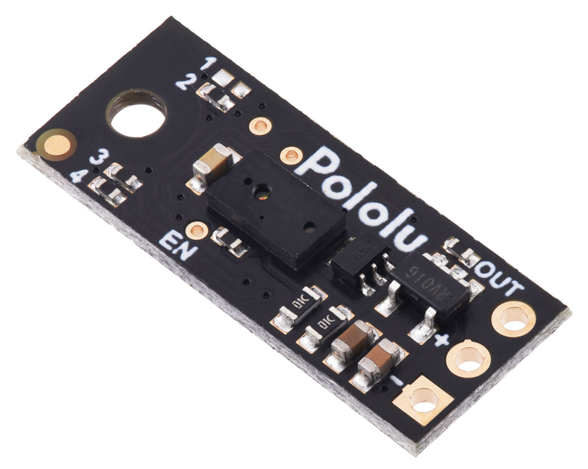
The Pololu Digital Distance Sensor (PW output, 50 cm max) uses a short-range lidar module and reports distance as the width of a digital pulse (similar to a hobby-servo signal). It’s ideal for reliable, fast obstacle detection and gives you an actual distance reading (3 mm resolution), perfect for lap direction detection at start and for close-range wall sensing.
 |
Specifications |
|---|---|
| Detection Range: 50 cm (depends on surface) | Type: Digital pulse width (HIGH-time encodes distance) |
| Voltage Supply: 3.0V – 5.5V | Current Draw: ~30 mA enabled, ~0.4 mA disabled (EN low) |
| Resolution: 3 mm (≈ 4 µs per 3 mm) | Update Rate: ~50–110 Hz (period ~20–9 ms) |
| Dimensions: 21.6mm × 8.9mm × 3.1mm | Weight: 1g |
| 🔗 Buy Here | Use Case: Start-line lap direction & close-range obstacle sensing for parking |
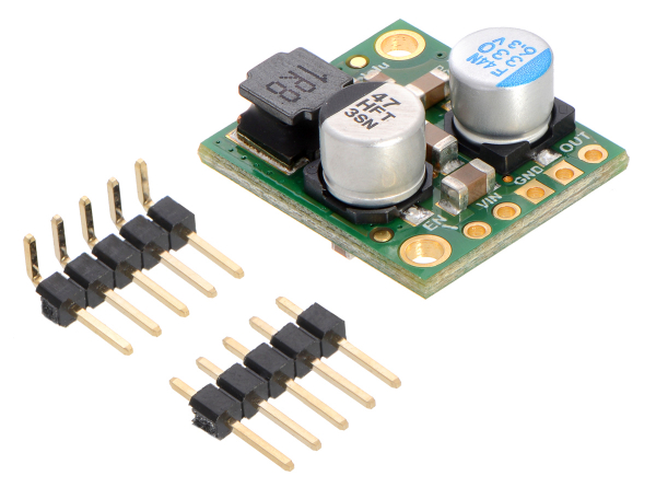
The D24V50F5 regulates the 11.1V Li-Po battery output to a stable 5V, ensuring safe power delivery to the Arduino, sensors, and camera. It prevents overvoltage damage and includes thermal & short-circuit protection for reliability.
 |
Specifications |
|---|---|
| Model: D24V50F5 | Input Voltage: 6V – 38V |
| Output Voltage: 5V | Output Current: 5A |
| Efficiency: Linear Regulator | Dropout Voltage: ~2V |
| Protection: Short-circuit & thermal shutdown | Mounting Type: Pins |
| 🔗 Buy Here | Function: Converts battery voltage to 5V |
| Electrical Schematics | PCB Design Cooper Traces | Chassis after Production |
|---|---|---|
 |
 |
 |
Advantages of a Custom PCB Chassis
✔ Organized layout ➜ Prevents loose connections & messy wiring
✔ Power stability ➜ Ensures consistent voltage supply to all components
✔ Compact design ➜ Reduces weight & optimizes space
✔ Reliability ➜ Minimizes risk of failure due to poor wiring
✔ Resistance ➜ Having a full PCB Chassis is more resistent compared to 3D printed parts glued or screwed together
| Item / Designators | Part | Supply | Typical Current | Peak Current | Notes |
|---|---|---|---|---|---|
| Arduino Nano ESP32 | MCU board | 5 V | 200 mA | 500 mA | Wi-Fi/BLE spikes |
| Steering Servo (MG90S) | Servo | 5 V | 120 mA | 500 mA | Peak at start/stall |
| OpenMV H7 Camera | Camera | 5 V | 300 mA | 400 mA | If on 3.3 V, power is lower |
| BMI088 | IMU | 3.3 V | 3.2 mA | 4 mA | Negligible |
| 1020 Coreless Impeller (via ESC) | Ducted fan | 7.4 V (VBAT) | 0.6 A | 1.8 A | Load-dependent; startup spikes high |
| Pololu 6 V 30:1 HPCB Motor | DC motor | ~6 V | ~120 mA (no-load) | ~1.6 A (stall) | Running current depends on load |
| IFX9201SG (IFX_A1) | Motor driver IC | 5 V (logic), VBAT (motor) | ~5 mA (logic) | ~10 mA (logic) | Motor current from VBAT |
| IRFR3411TRPBF-VB (Q1) | N-MOSFET | VBAT/5 V | ≈0 mA DC | — | Gate draw ≈0 DC |
| 78M05 (U5) | 5 V LDO | 7.4 V→5 V | 6 mA quiescent | 6 mA | Plus it sources all 5 V loads |
| LED5 | XL-1608SURC-06 | 5 V | 5 mA | 10 mA | Red, assumed 5 mA |
| LED1–LED4 | XL-1608UBC-04 | 5 V | 4×5 mA = 20 mA | ~40 mA | Blue, assumed 5 mA each |
| R8,R9,R10,R4–R7 | Resistors | — | ~0 mA | — | Included via LED rows |
| C3,C4,C5,C6,C8 | Capacitors | — | 0 | — | Reactive only |
| RST, START (B3U-1000P) | Tact switches | — | 0 | — | No DC draw |
The motor driver is based on the Infineon IFX9201SG, which allows us to directly manage the motor with only two control signals: a PWM pin that regulates speed, and a direction pin that selects forward or reverse rotation. Thanks to this chip’s integrated design, no external library was required for motor control.
We implemented a set of functions within our control system: one to initialize the driver, one to control motor velocity, and another to stop it effectively using an active braking routine. The function move(int speed) takes an input in the range −255 to +255. The absolute value of the input is written to the PWM channel, while the sign determines the motor’s rotation direction. A dedicated stop_motor() function applies a short reverse torque pulse before setting the PWM duty cycle to zero, ensuring the robot stops quickly without uncontrolled coasting.
Since the robot is powered by an ESP32, PWM signals must be generated using the LEDC hardware utility, which provides stable and precise duty cycles.
void motor_driver_setup() {
  pinMode(PWMA, OUTPUT);
  pinMode(DIRA, OUTPUT);
  ledcSetup(PWM_MOTOR_CHANNEL, PWM_MOTOR_FREQ, PWM_MOTOR_RESOLUTION);
  ledcAttachPin(PWMA, PWM_MOTOR_CHANNEL);
  move(0);
}

void move(int speed) {
  ledcWrite(PWM_MOTOR_CHANNEL, abs(speed));
  digitalWrite(DIRA, speed > 0 ? LOW : HIGH);
}

void stop_motor() {
  move(-3);
  delay(100);
  move(0);
}
For odometry, the motor includes an encoder. We implemented an interrupt-based approach to count ticks in real time, avoiding the need for a dedicated library. The encoder setup attaches an interrupt on the rising edge of channel A, and the distance traveled is computed from tick counts.
In this configuration, the encoder provides 12 counts per revolution, and by applying the gear ratio, wheel diameter, and π, we obtain a conversion factor of MM_PER_TICK = 1.8326. This enables the robot to measure traveled distance with centimeter-level accuracy, which is crucial for precise maneuvers during navigation.
void encoder_setup() {
  // Enable pull-ups so A/B never float
  pinMode(ENCODER_A, INPUT_PULLUP);
  pinMode(ENCODER_B, INPUT_PULLUP);
  // Attach only A’s rising edge:
  attachInterrupt(digitalPinToInterrupt(ENCODER_A), encoderISR, RISING);
  encoder_ticks = 0;
}

float read_cm() {
  noInterrupts();
  int32_t t = encoder_ticks;
  interrupts();

  float dist_mm = t * MM_PER_TICK;
  float dist_cm = dist_mm / 10.0f;
  //Serial.printf("ticks=%ld  dist_cm=%.2f\n", t, dist_cm);
  return dist_cm;
}The impeller is responsible for generating downforce, which increases stability and traction when the robot operates at high speed. To control it, we use an RFR3411 MOSFET, wired as a low-side switch. This MOSFET can safely handle the high current required by the impeller, while allowing speed control via PWM modulation.
Only a single PWM pin from the ESP32 is needed to drive the MOSFET gate. The PWM duty cycle determines how much power is applied to the impeller:
0 = off
255 = full speed
Two functions were implemented for simplicity: one for initializing the PWM channel and one for setting the impeller speed.
void impeller_setup() {
  pinMode(PWM_IMPELLER, OUTPUT);
  ledcSetup(PWM_IMPELLER_CHANNEL, PWM_IMPELLER_FREQ, PWM_IMPELLER_RESOLUTION);
  ledcAttachPin(PWM_IMPELLER, PWM_IMPELLER_CHANNEL);
}

void setImpeller(int _pwm) {
  ledcWrite(PWM_IMPELLER_CHANNEL, constrain(_pwm, 0, 255));
}The steering system is controlled by a MG90S servo, which adjusts the angle of the front wheels. This enables the robot to follow precise paths while maintaining stability during turns.
The servo is connected directly to the ESP32 and driven using the ESP32Servo.h library interface. To ensure consistent and safe motion, we defined three reference positions:
STEERING_LEFT = 140
STEERING_CENTER = 85
STEERING_RIGHT = 40
These values were experimentally calibrated to match the geometry of the steering mechanism.
The function steering_servo_setup() attaches the servo to its pin, performs a left–right sweep to verify operation, and finally centers it. This ensures that the robot always starts in a straight-line configuration.
The function steer(double steering_angle) accepts an input in the range [-1, 1], representing normalized steering:
-1 = maximum right
0 = centered
+1 = maximum left
The input is first clamped to stay within the allowed range, then mapped to the calibrated servo values using map_double. This abstraction allows higher-level controllers (such as PID) to provide normalized outputs without directly worrying about servo limits.
void steering_servo_setup() {
  steeringServo.attach(STEERING_SERVO);
  delay(100);

  steeringServo.write(STEERING_LEFT);
  delay(300);
  steeringServo.write(STEERING_RIGHT);
  delay(300);
  steeringServo.write(STEERING_CENTER);
  delay(300);
}

void steer(double steering_angle) {
  // Clamp input between -1 and 1
  if (steering_angle > 1)  steering_angle = 1;
  if (steering_angle < -1) steering_angle = -1;

  // Map to servo range
  steering_angle = map_double(steering_angle, -1, 1, STEERING_LEFT, STEERING_RIGHT);
  steeringServo.write(steering_angle);
}To keep the robot on a straight path and execute precise turns, we rely on the Bosch BMI088 Inertial Measurement Unit (IMU). This sensor combines a high-resolution accelerometer and gyroscope, and in our case we primarily use the Z-axis gyroscope for yaw angle estimation.
During initialization, the function gyro_setup() configures the BMI088 via I²C communication. The accelerometer is set to a ±6 g range at 200 Hz, while the gyroscope is set to ±2000 °/s at 400 Hz with a 47 Hz bandwidth. These parameters provide a good balance between responsiveness and noise filtering.
A key challenge with gyroscopes is drift — the tendency of small measurement errors to accumulate over time. To correct this, the setup function performs a calibration routine: for a predefined duration (DRIFT_TEST_TIME), the sensor’s output is averaged while the robot is stationary. The resulting bias (drifts_z) is subtracted from all subsequent readings.
void gyro_setup() {
  // 1) Wire + basic init
  Wire.begin();
  imu.initialize();

  imu.setAccScaleRange(RANGE_6G);
  imu.setAccOutputDataRate(ODR_200);       // 200 Hz accel
  imu.setAccPoweMode(ACC_ACTIVE);

  imu.setGyroScaleRange(RANGE_2000);
  imu.setGyroOutputDataRate(ODR_400_BW_47); // 400 Hz, BW=47 Hz
  imu.setGyroPoweMode(GYRO_NORMAL);

  if (!imu.isConnection()) {
    if (debugGyro) {
      Serial.println("BMI088 connection failed!");
    }
    return;
  }

  if (debugGyro) Serial.println("Starting gyro drift calculation...");
  double start = millis();
  gyro_last_read_time = start;
  gz = 0;

  while (millis() - start < DRIFT_TEST_TIME * 1000) {
    double now = millis();
    double dt = (now - gyro_last_read_time) * 0.001; // s
    float rate = imu.getGyroscopeZ();                // °/s
    gz += rate * dt;                                 // accumulate degrees
    gyro_last_read_time = now;
  }

  drifts_z = gz / DRIFT_TEST_TIME;  // average °/s
  if (debugGyro) {
    Serial.print("Drift test done! drifts_z = ");
    Serial.print(drifts_z, 6);
    Serial.println(" °/s");
  }

  // reset integration
  gz = 0;
  gyro_last_read_time = millis();
}
The function read_gyro_data() must be called continuously in the control loop. It computes the elapsed time dt, reads the current angular rate from the BMI088, subtracts the drift offset, and integrates the result into gz, which represents the robot’s absolute yaw angle in degrees. This value is used directly in the PID controller for heading correction.
void read_gyro_data() {
  // call this frequently (e.g. every loop)
  double now = millis();
  double dt  = (now - gyro_last_read_time) * 0.001; // s
  float rate = imu.getGyroscopeZ();              // °/s
  double corrected = rate - drifts_z;               // drift-compensated
  gz += corrected * dt;                             // integrate to degrees
  gyro_last_read_time = now;

  if (debugGyro) {
    Serial.print("Gyro angle (°): ");
    Serial.println(gz, 4);
  }
}The robot integrates four Pololu PWM distance sensors, placed on the front, back, left, and right sides of the chassis. Each sensor outputs a pulse width signal, where the duration is proportional to the measured distance. This gives us precise range data without requiring complex communication protocols.
The function distanceSensorPin(DistanceDir d) maps each logical direction (FRONT_DIR, LEFT_DIR, RIGHT_DIR, BACK_DIR) to its corresponding analog pin. Using pulseIn(), we measure the pulse width, and the helper function pulseToMM() converts it into millimeters based on the calibration constants:
PW_OFFSET_US – offset at ~0 mm (typically ~1000 µs)
PW_US_PER_MM – scaling factor (1 µs per mm)
PULSE_TIMEOUT_US – maximum waiting time for a valid pulse (30 ms)
If no valid pulse is received, the function returns -1 to indicate a timeout.
// ======= Pololu PWM Distance Sensor Settings =======
static const float PW_OFFSET_US   = 1000.0f; // microseconds offset at ~0 mm
static const float PW_US_PER_MM   = 1.0f;    // microseconds per millimeter
static const unsigned long PULSE_TIMEOUT_US = 30000UL; // 30 ms timeout

// ======= Map direction to the correct pin =======
static inline int distanceSensorPin(DistanceDir d) {
  switch (d) {
    case FRONT_DIR: return PWM_DIST_FRONT; // A0
    case LEFT_DIR:  return PWM_DIST_LEFT;  // A3
    case RIGHT_DIR: return PWM_DIST_RIGHT; // A1
    case BACK_DIR:  return PWM_DIST_BACK;  // A2
  }
  return PWM_DIST_FRONT;
}

// ======= Read pulse in microseconds =======
static inline unsigned long readPulseUS(int pin) {
  pinMode(pin, INPUT);
  return pulseIn(pin, HIGH, PULSE_TIMEOUT_US);
}

// ======= Convert pulse width to millimeters =======
static inline float pulseToMM(unsigned long pw_us) {
  if (pw_us == 0) return -1.0f; // timeout
  float mm = (float(pw_us) - PW_OFFSET_US) / PW_US_PER_MM;
  if (mm < 0) mm = 0;
  return mm;
}Once the robot can move and steer, it also needs to see and react to the environment. For this, we use an OpenMV camera module, connected via UART protocol. This allows the camera to handle the heavy work of image processing and only send compact messages (like colors, cubes, or angles) to the ESP32.
The camera is wired to the ESP32 as follows:
- Camera TX (P4) → ESP32 RX (D0)
- Camera RX (P5) → ESP32 TX (D1)
Both devices must share the same baud rate (19200). On the ESP32 side, we use SoftwareSerial for communication, while on the camera side, UART(3, 19200) is initialized.
Arduino code:
// UART to OpenMV (SoftwareSerial on D0/D1)
#include <SoftwareSerial.h>
SoftwareSerial cameraSerial(D0, D1); // RX=D0, TX=D1

String receivedMessage;

void comm_setup() {
  Serial.begin(9600);
  cameraSerial.begin(19200);          // must match OpenMV baudrate
  receivedMessage = "";
  // (optional) small flush
  while (cameraSerial.available()) cameraSerial.read();
}

void loop() {
  // ... control loop stuff ...

  // Execute pending commands from camera
  while (cameraSerial.available() > 0) {
    char c = cameraSerial.read();
    if (c == '\n') {
      // Optionally skip commands while parking
      if (CASE != PARK) {
        execute_command(receivedMessage); // handle "S<angle>", "BLUE", "ORANGE", "RED", "GREEN", "BLACK", "1", "2"
      }
      receivedMessage = "";
    } else {
      receivedMessage += c;
    }
  }
}
Camera code:
We use UART(3, 19200) on OpenMV (P4=TX, P5=RX). Baud must match the Arduino side.
from pyb import UART
uart = UART(3, 19200)
# 3 → uses P4 (TX) and P5 (RX)
# 19200 → baud rate, must match Arduino
Arduino listens and executes messages line-by-line (ending with \n). Camera only sends.
We configure the camera for RGB565, QVGA (320×240), flipped to match mounting, and fixed exposure/gain/WB for consistent LAB thresholds.
import sensor, time
sensor.reset()
sensor.set_pixformat(sensor.RGB565)
sensor.set_framesize(sensor.QVGA)     # 320x240
sensor.set_vflip(True)
sensor.set_hmirror(True)

sensor.set_auto_gain(False)           # must be off for color tracking
sensor.set_auto_whitebal(False)       # must be off for color tracking
sensor.set_auto_exposure(False, exposure_us=10000)  # ~10ms
sensor.skip_frames(time=2000)

clock = time.clock()
Why fixed exposure? It keeps color thresholds stable across frames and lighting.
Color thresholds (LAB) for red/green cubes, blue/orange lines, black walls. We also define ROIs to look only where each object should appear (faster + fewer false positives).
# ---- LAB thresholds ----
red_threshold    = [(32, 54, 40, 67, 17, 63)]
green_threshold  = [(36, 69, -56, -21, -19, 32)]
blue_threshold   = [(9, 76, -45, 27, -57, -8)]
orange_threshold = [(62, 91, -3, 43, 5, 69)]
pink_threshold   = [(30, 70, 10, 60, -15, 15)]
black_threshold  = [(0, 37, -26, 7, -17, 11)]

# ---- Regions of Interest ----
img_h, img_w = sensor.height(), sensor.width()
cubes_roi      = (0, int(img_h * 0.4),  img_w,        int(img_h * 0.6))  # bottom area
lines_roi      = (5, int(img_h * 0.5),  img_w - 10,   int(img_h * 0.4))  # lower band
wall_roi       = (50, int(img_h * 0.5 - 18), img_w - 100, int(img_h * 0.2 - 10))
final_wall_roi = (30, 80, img_w - 60, int(img_h - 60))
Minimum areas to reject noise and a simple PD setup for cube following.
min_cube_size       = 300
min_line_size       = 800
min_area            = 10
min_valid_cube_area = 450
black_wall_min_area = 7000
final_black_wall_min_area = 9000
min_black_height    = 39

kp_cube = 0.21
kd_cube = 2.4
pid_error = 0.0
pid_last_error = 0.0
follow_threshold = 4100

direction = 0  # 0 = unset, 1 = LEFT(blue), 2 = RIGHT(orange)

def get_largest_blob(blobs):
    return max(blobs, key=lambda b: b.area(), default=None)
Every frame, we:
- Detect walls (parking / turn signal) → send
"BLACK" - Detect cubes (red/green) → send
S<error>for follow, orRED/GREENwhen very close - Detect lines (blue/orange) → send
"BLUE"/"ORANGE"and set direction (1/2) - Always send the current direction ("1"/"2") for sync
while True:
    clock.tick()
    img = sensor.snapshot()
    target_x = img_w // 2

    # ---- Walls / parking ----
    black_blobs = img.find_blobs(black_threshold, roi=final_wall_roi,
                                 pixels_threshold=final_black_wall_min_area,
                                 area_threshold=final_black_wall_min_area, merge=True)
    black_blob = get_largest_blob(black_blobs)
    if black_blob and black_blob.h() >= min_black_height:
        uart.write("BLACK\n")

    # ---- Cubes (red/green) ----
    red_blobs   = img.find_blobs(red_threshold,   roi=cubes_roi,
                                 pixels_threshold=min_cube_size,
                                 area_threshold=min_cube_size, merge=True)
    green_blobs = img.find_blobs(green_threshold, roi=cubes_roi,
                                 pixels_threshold=min_cube_size,
                                 area_threshold=min_cube_size, merge=True)

    red_cube   = get_largest_blob([b for b in red_blobs   if b.area() >= min_valid_cube_area])
    green_cube = get_largest_blob([b for b in green_blobs if b.area() >= min_valid_cube_area])

    candidates = []
    if red_cube:   candidates.append(('RED',   red_cube))
    if green_cube: candidates.append(('GREEN', green_cube))

    if candidates:
        color, cube = max(candidates, key=lambda x: x[1].area())
        # normalized horizontal error in [-1..1]
        error = (cube.cx() - target_x) / float(target_x)
        pid_error = kp_cube * error + kd_cube * (error - pid_last_error)
        pid_last_error = error

        if cube.area() < follow_threshold:
            uart.write("S{:+.3f}\n".format(error))   # steer hint for FOLLOW_CUBE
        else:
            uart.write(color + "\n")                 # close: just report color

    # ---- Lines (blue/orange) ----
    blue_blobs   = img.find_blobs(blue_threshold,   roi=lines_roi,
                                  pixels_threshold=min_line_size,
                                  area_threshold=min_line_size, merge=True)
    orange_blobs = img.find_blobs(orange_threshold, roi=lines_roi,
                                  pixels_threshold=min_line_size,
                                  area_threshold=min_line_size, merge=True)

    blue_line   = get_largest_blob([b for b in blue_blobs])
    orange_line = get_largest_blob([b for b in orange_blobs])

    chosen = None
    if blue_line and orange_line:
        chosen = "BLUE" if blue_line.area() > orange_line.area() else "ORANGE"
    elif blue_line:
        chosen = "BLUE"
    elif orange_line:
        chosen = "ORANGE"

    if chosen:
        uart.write(chosen + "\n")
        if direction == 0:
            direction = 1 if chosen == "BLUE" else 2

    # ---- Always send current turn direction ----
uart.write(str(direction) + "\n")During the Open Round, our robot follows a straight trajectory using a PID controller based on gyro yaw, ensuring stable movement. To determine turns, the camera detects Orange and Blue lines on the track:
- Orange Line ➜ Right Turn
- Blue Line ➜ Left Turn
- The turn is executed when the robot reaches an approximate distance from the front black wall.
The camera captures frames in RGB565 format and processes color blobs using LAB thresholds to detect relevant track elements. Below is a snippet of the camera’s core logic that identifies track lines and determines turning direction:
# Detect Blobs
red_blobs = img.find_blobs(red_threshold, roi=cubes_roi, pixels_threshold=min_cube_size, area_threshold=min_cube_size, merge=True)
green_blobs = img.find_blobs(green_threshold, roi=cubes_roi, pixels_threshold=min_cube_size, area_threshold=min_cube_size, merge=True)
blue_blobs = img.find_blobs(blue_threshold, roi=lines_roi, pixels_threshold=min_line_size, area_threshold=min_line_size, merge=True)
orange_blobs = img.find_blobs(orange_threshold, roi=lines_roi, pixels_threshold=min_line_size, area_threshold=min_line_size, merge=True)
black_blobs = img.find_blobs(black_threshold, roi=cubes_roi, pixels_threshold=min_cube_size, area_threshold=min_cube_size, merge=True)

...

# Determine Direction
if direction == 0:
    if orange_line and not is_invalid_orange(orange_line, red_blobs):
        direction = 2  # Orange line first ➜ turn right
    elif blue_line:
        direction = 1  # Blue line first ➜ turn left

# Send Direction Command
uart.write(str(direction) + '\n')
In the final round, we extend our open rount algorithm by adding real‐time cube detection, following, and avoidance algorithms. The OpenMV H7 camera handles live frames processing and sends compact UART messages to the Arduino Nano ESP32. On the Arduino, incoming UART messages drive a four‐state algorithm: in PID, the robot adjust to hold a straight heading by using a PD on the gyro and turns 90° whenever it receives a BLACK signal (lap turning point in each corner). In FOLLOW_CUBE, the camera’s S<corrected_servo> message directly sets the servo angle to chase the closest visible cube; if no follow message arrives within 250-500 ms, it returns to PID as the cube might have been passed or lost from the view. When a proximity trigger (RED or GREEN, R or G) arrives, it switches to AVOID_CUBE, executes a 37° turn plus an 8 cm clear‐away while holding that heading, then enters AFTER_CUBE to reallign on gyro while moving back to center section of each side of the map, and to flush the leftover commands before reverting to PID.
This switch statement runs inside void loop() and decides what the robot does in each of the four states.
switch (currentState) {

  case PID:
    {
      // PID straight‐drive, maintain heading using gyro PD
      double err = current_angle_gyro - gz;
      pid_error        = (err) * kp + (pid_error - pid_last_error) * kd;
      pid_last_error   = pid_error;
      steer(pid_error);
      move(robot_speed);
      break;
    }

  case FOLLOW_CUBE:
    {
      // If no follow command arrives within 250-500ms, go back to gyro PD
      if (millis() - last_follow_cube > FOLLOW_CUBE_LOST_TIME) {
        currentState = PID;
      }
      // Otherwise, steer directly toward the cube, so we do active cube following, using a PD that runs on the camera
      steer(follow_cube_angle);
      move(robot_speed);
      break;
    }

  case AVOID_CUBE:
    {
      // Perform the hard coded avoidance maneuver
      pass_cube(cube_avoid_direction);
      break;
    }

  case AFTER_CUBE:
    {
      // Return to PID after getting to be straight again, while ignoring all commands
      while (millis() - last_cube_time > 1500) {
        read_gyro_data();
        double error = current_angle_gyro - gz;
        pid_error = (error)*kp + (pid_error - pid_last_error) * kd;
        pid_last_error = pid_error;
        if (debug == true) {
          Serial.print(current_angle_gyro);
          Serial.print("     |      ");
          Serial.print(turn_direction);
          Serial.print("     |      ");
          Serial.print(gz);
          Serial.print("     |      ");
          Serial.println(robot_speed);
        }
        steer(pid_error);
        move(robot_speed);
      }
      currentState = PID;
      cameraSerial.flush();
      break;
    }
}
PID:
- Uses a PD loop on the integrated gyro yaw (
gz) vs. desired heading (current_angle_gyro). - Calls
steer(pid_error)andmove(robot_speed)to drive straight.
FOLLOW_CUBE:
- If we haven’t received a new
"S…\n"follow message for at least 250-500 ms, assume the cube is lost or passed and switch back to PID. - Otherwise, use
follow_cube_angle(sent by the camera) to set the servo and follow the cube.
AVOID_CUBE:
- Calls
pass_cube(cube_avoid_direction), which executes a turn to left or right based on the cube color. This code sequence is hard coded.
AFTER_CUBE:
- Return to PID after getting to be straight again, while ignoring all commands.
This function is called whenever a complete line arrives over UART. It selects which state to enter (PID, FOLLOW_CUBE, AVOID_CUBE) or adjusts gyro target angle on a BLACK message by adding or removing 90 degrees, based on the turn direction.
void execute_command(String cmd) {
  cmd.trim();
  cmd.toUpperCase();

  // “S…” steering to follow cube ➜ FOLLOW_CUBE
  if (cmd.startsWith("S") && RUN_MODE == 1) {
    float val = cmd.substring(1).toFloat();
    follow_cube_angle = val;
    currentState      = FOLLOW_CUBE;
    last_follow_cube  = millis();

    if (debug) {
      Serial.print("FOLLOW_CUBE angle ➜ ");
      Serial.println(follow_cube_angle);
    }
    return;
  }

  // Map color words to one letter commands and set turn_direction on first BLUE/ORANGE
  char c = cmd.charAt(0);
  if      (cmd.indexOf("BLACK")  != -1) { c = 'B'; }
  else if (cmd.indexOf("BLUE")   != -1) { c = 'L'; lastLineDetectedTime = millis(); if (turn_direction == 0) turn_direction = -1; }
  else if (cmd.indexOf("ORANGE") != -1) { c = 'O'; lastLineDetectedTime = millis(); if (turn_direction == 0) turn_direction =  1; }
  else if (cmd.indexOf("RED")    != -1) { c = 'R'; }
  else if (cmd.indexOf("GREEN")  != -1) { c = 'G'; }
  else if (cmd.indexOf("PINK")   != -1) { c = 'P'; }
  else { return; }  // Ignore any other strings

  // “BLACK” turn 90° if in PID
  if (currentState == PID) {
    if (c == 'B' || (millis() - lastLineDetectedTime > 1800 && lastLineDetectedTime > 0)) {
      if (millis() - lastTurnTime < 1000) {
        if (debug) Serial.println("Ignoring repeated 'B' command due to cooldown.");
        return;
      }
      if (debug) Serial.println("Received 'BLACK' command. Turning 90°...");
      current_angle_gyro += turn_direction * 90;
      turn_count++;
      lastTurnTime         = millis();
      lastLineDetectedTime = 0;
      return;
    }
  }

  // “RED” or “GREEN” close to a cube and need to avoid it ➜ AVOID_CUBE
  if ((c == 'R' || c == 'G') && millis() - last_cube_time >= AVOIDANCE_DRIVE_TIME) {
    cube_avoid_direction = (c == 'R') ? 'L' : 'R';  // 'R' means turn left, 'G' turn right
    currentState         = AVOID_CUBE;
    last_cube_time       = millis();
    if (debug) {
      Serial.print("AVOID_CUBE dir ➜ ");
      Serial.println(cube_avoid_direction);
    }
    return;
  }

  if (debugcam) {
    Serial.print("Ignored cmd ➜ ");
    Serial.println(cmd);
  }
}
“S…” (e.g. "S+0.120\n"):
- Parses the float after
S, setsfollow_cube_angleto the value that was sent after S character, and switches to FOLLOW_CUBE. - Records the time to
last_follow_cubeso we know how long it has been since the camera last issued a “follow” command.
“BLACK”:
- Only when in PID, add or substract 90° based on the lap direction, by adjusting
current_angle_gyro += ±90. - Increment
turn_countand enforce a 1 s cooldown to avoid repeated turning signals.
“RED” or “GREEN”:
- When getting to close to a cube, it sets
cube_avoid_directionbased on the cube color and enter AVOID_CUBE.
When in AVOID_CUBE, the robot executes a hardcoded movement, that includes a fixed turn + move forward maneuver to avoid the cube, then transitions to AFTER_CUBE, that alligns the robot for doing PID and follow the next cube.
void pass_cube(char cube_direction) {
  read_gyro_data();
  // Convert 'R' ➜ +1 (turn left), 'G' ➜ -1 (turn right)
  int sign = (cube_direction == 'R') ? 1 : -1;

  double start_angle  = gz;
  double target_angle = start_angle - sign * AVOIDANCE_ANGLE;

  // Turn ~37° away from cube
  move_until_angle(robot_speed, target_angle);

  // Drive ~8 cm forward while holding that heading
  move_cm_gyro(8, robot_speed, target_angle);

  // Move to AFTER_CUBE case
  last_cube_time = millis();
  currentState   = AFTER_CUBE;

  // Discard any leftover UART messages before returning to PID
  flush_messages();
}In the OpenMV python script, we detect the largest visible red or green blob in the bottom 40% section of the frame, while computing a PD steering error, and send either a small follow command "S±pid_error\n" or an avoid trigger "RED\n"/"GREEN\n" over UART.
Choose Closest Cube & Follows it by using a PD algorithm
# ---- Choose Closest Cube (largest red or green) ----
candidates = []
if red_cube:   candidates.append(('R', red_cube))
if green_cube: candidates.append(('G', green_cube))

if candidates:
    # Pick the cube (red or green) with the largest area
    color_char, cube = max(candidates, key=lambda x: x[1].area())
    area = cube.area()
    col  = (255,0,0) if color_char == 'R' else (0,255,0)

    # Draw rectangle and crosshair on the selected cube
    img.draw_rectangle(cube.rect(), color=col)
    img.draw_cross(cube.cx(), cube.cy(), color=col)
    img.draw_string(cube.x(), cube.y() + cube.h() - 10,
                    str(area), color=col)

    # Compute normalized horizontal error in [-1, 1]
    error = (cube.cx() - target_x) / float(target_x)
    pid_error = kp_cube * error + kd_cube * (error - pid_last_error)
    pid_last_error = error

    if area < follow_threshold:
        # Send “S±error\n” to indicate a small servo correction (➜ FOLLOW_CUBE)
        uart.write("S{:+.3f}\n".format(error))
        if DEBUG:
            print("{} FOLLOW ➜ err:{:+.3f}, pid:{:+.3f}, area:{}".format(
                  "RED" if color_char == 'R' else "GREEN",
                  error, pid_error, area))
    else:
        # At close range, send just “RED\n” or “GREEN\n” to trigger avoidance
        uart.write(("RED\n" if color_char == 'R' else "GREEN\n"))
        if DEBUG:
            print("{} CLOSE ➜ area {} >= {}".format(
                  "RED" if color_char == 'R' else "GREEN",
                  area, follow_threshold))

At the start of the round, our robot is placed in the designated parking zone (the parking zone is 1.5x robot lenght). To determine the direction of the first lap (clockwise or counterclockwise), we use the 2 distance sensors placed on left and right side of our robot, the one that sees the wall further away will be the side to exit and do the laps.
Once the direction is determined, the robot performs an initial steering exit maneuver (to left or right) using our custom PD-based turning function:
// Start from parking
if (RUN_MODE == 1) {
  if (readDistanceMM(LEFT_DIR, 3) < readDistanceMM(RIGHT_DIR, 3)) {  // exit right
    move_until_angle_max(exit_speed, 75);

    move(65);
    delay(100);

    turn_direction = 1;
    move_until_angle_max(exit_speed, 0);

    move_straight_on_gyro(-robot_speed, 900); // allign the robot to be able to pass cubes
  } else {  // exit left
    move_until_angle_max(exit_speed, -70);

    move(65);
    delay(100);

    turn_direction = -1;
    move_until_angle_max(exit_speed, 0);

    move_straight_on_gyro(-robot_speed, 1800); // allign the robot to be able to pass cubes
  }
}
The robot turns ~75° toward the main track depending on the detected direction. Following this parking exit, the robot enters its standard operating state:
- If it detects a cube, it enters FOLLOW_CUBE mode, where it tries to center itself on the cube using a PD algorithm.
- If the cube gets too close, it enters AVOID_CUBE mode, passing the cube left or right based on its color.
- After AVOID_CUBE, it automatically enters AFTER_CUBE, where it centers itself on the center of the track to prepare for searching the next cube.
- When no cube is detected, it enters PID mode, in which it simply navigates straight using the gyro—just as in qualification runs.
At the end of the run, once the robot has completed 12 turns in RUN_MODE 1 (final run mode), it transitions into the parallel parking sequence. This routine is fully deterministic and relies on both front and back distance sensors together with the gyro angle to achieve a repeatable and precise result. The sequence consists of four main phases:
1. Front-Wall Alignment
The robot first drives forward until it reaches a target offset from the front wall, ensuring a consistent starting position for the parking maneuver.
- Left course: 470 mm from the front wall
- Right course: 460 mm from the front wall
This distance lock guarantees that the robot always starts the parking procedure at the same longitudinal reference point.
2. Lane Reorientation
Next, the robot performs a 90° snap turn into the parking lane:
- Heading update:
current_angle_gyro += turn_direction * 90 - Correction: On left courses, an additional
-3°trim is applied for drift compensation.
This ensures the chassis is now parallel to the parking lane wall.
3. Lane Squaring & Staging
The robot then stabilizes its position inside the lane using a two-step process:
- Moves forward 200 mm while holding the new heading (gyro-straight).
- Aligns on the rear wall by driving backwards until the back sensor reads 300 mm.
Finally, it advances to a staging distance inside the lane, preparing for the parking maneuver:
- Left course: 900 mm from the front wall
- Right course: 1590 mm from the front wall
This places the robot in the correct position to start the 3-move parallel park.
4. Three-Maneuver Parallel Parking
The actual parallel parking is executed as three steering sweeps:
-
Left Course (
turn_direction = -1)- Reverse Arc: Turn at
-75°relative to prking spot. - Straighten Backwards: Reduce angle to
-5°. - Forward Tuck: Correct forward sweep to
+5°.
- Reverse Arc: Turn at
-
Right Course (
turn_direction = +1)- Reverse Arc: Turn at
+75°relative to parking spot. - Straighten Backwards: Reduce angle to
+5°. - Forward Tuck: Correct forward sweep to
-2°.
- Reverse Arc: Turn at
This sequence positions the robot in the parking zone, parallel to the wall and within the designated area.
5. Final Stop
Once the three-step maneuver is complete, the robot:
- Centers the steering servo.
- Cuts motor power (
move(0)). - Enters a 20-second idle state, ending the run.
Code (for both lap directions):
...
if (turn_count == 12 && RUN_MODE == 1) {
  move_straight_on_gyro(robot_speed, 500);
  if (turn_direction == -1) {
    move_to_distance(FRONT_DIR, 470.0f, 10.0f, 55, current_angle_gyro);
    current_angle_gyro += turn_direction * 90;
    current_angle_gyro -= 3;

    move_until_angle_max(60, current_angle_gyro);
    move_straight_on_gyro(robot_speed, 200);
    move_to_distance(BACK_DIR, 300.0f, 10.0f, -55, current_angle_gyro);
    move_to_distance(FRONT_DIR, 900.0f, 10.0f, 55, current_angle_gyro);

    // sensu de stanga
    move_until_angle_max(-60, (current_angle_gyro) - 75);
    move_until_angle_max(-60, (current_angle_gyro) - 5);
    move_until_angle_max(60, (current_angle_gyro) + 5);
  } else {
    move_to_distance(FRONT_DIR, 460.0f, 10.0f, 55, current_angle_gyro);
    current_angle_gyro += turn_direction * 90;

    move_until_angle_max(60, current_angle_gyro);
    move_straight_on_gyro(robot_speed, 200);
    move_to_distance(BACK_DIR, 300.0f, 10.0f, -55, current_angle_gyro);
    move_to_distance(FRONT_DIR, 1590.0f, 10.0f, 55, current_angle_gyro);

    move_until_angle_max(-63, (current_angle_gyro)+75);
    move_until_angle_max(-63, (current_angle_gyro)+5);
    move_until_angle_max(60, (current_angle_gyro)-2);
  }

  steeringServo.write(STEERING_CENTER);
  delay(300);

  move(0);
  delay(20000);
}
...🔗 Click here to watch the video on YouTube(without music) 🔗 Click here to watch the video on YouTube(with music)
We have optimized our robot for performance vs. cost efficiency. The total cost includes motors, sensors, electronics, PCB, 3D printing and custom parts.
| Component | Quantity | Unit Price ($) | Total ($) |
|---|---|---|---|
| Arduino Nano ESP32 | 1 | 21.42 | 21.42 |
| Drive Motor 6V (30:1 HPCB) | 1 | 22.45 | 22.45 |
| IFX9201SG Motor Driver | 1 | 19.92 | 19.92 |
| Steering Servo (MG90S) | 1 | 4.05 | 4.05 |
| OpenMV H7 Camera | 1 | 80.00 | 80.00 |
| Gyroscope (BMI088) | 1 | 8.50 | 8.50 |
| Pololu Distance Sensor | 4 | 17.95 | 71.80 |
| LiPo Battery (2S 300mAh) | 1 | 5.60 | 5.60 |
| D24V50F5 Voltage Regulator | 1 | 29.95 | 29.95 |
| Custom Silicone Wheels | 4 | 9.24 | 36.96 |
| RC Differential | 1 | 4.00 | 19.04 |
| Experimental Parts | 35.00 | 35.00 | |
| TOTAL COMPONENT COST | - | - | 354.39 |
Experimental Parts
-
MPU6050
A compact IMU that's easy to integrate. However, it comes with several disadvantages, such as significant drifting over short time, even when using a Kalman filter for correction. -
Pololu 30:1 Micro Metal Gearmotor
A powerful and compact motor. The main issue is that it was the no encoder version and couldn't add the encoder, making it difficult to achieve precise control.
| PCB Component | Quantity | Unit Price ($) | Total ($) |
|---|---|---|---|
| PCB Manufacturing (JLCPCB) | 5 | 7.82 | 39.10 |
| PCB Assembly (JLCPCB) | 5 | 14.55 | 72.75 |
| TOTAL PCB COST | - | - | 111.85 |
| 3D Printed Parts | Quantity | Unit Price ($) | Total ($) |
|---|---|---|---|
| 1000g filament (PLA and PLA-CF) | 1 | 20.00 | 20.00 |
| TOTAL 3D PRINTING COST | - | - | 20.00 |
| Material | Quantity | Unit Price ($) | Total ($) |
|---|---|---|---|
| M3 Screws & Nuts Set | - | - | 4.00 |
| Wiring & Connectors | - | - | 5.00 |
| TOTAL OTHER MATERIALS COST | - | - | 9.00 |
| Category | Total Cost ($) |
|---|---|
| Components | 325.24 |
| PCB (JLCPCB + Components) | 111.85 |
| 3D Printing | 20.00 |
| Other Materials | 9.00 |
| TOTAL PROJECT COST | 466.09 |
*Prices are approximate, based on current market prices.
Below is a list of external images used in this repository.
- Arduino Nano ESP32
- BMI088 IMU Sensor
- OpenMV H7 Camera
- Pololu 30:1 Gearmotor
- MG90S Steering Servo
- D24V50F5 Voltage Regulator
- 2S 300mAh Li-Po Battery
- IFX9201SG Motor Driver
- Pololu Distance Sensor
License – All Rights Reserved

Copyright (c) 2025 **Popescu Filimon Andrei Cosmin**
All rights reserved.

This software and all associated files are the exclusive property of the copyright holder.

* You **may not copy, modify, merge, publish, distribute, sublicense, or sell** any part of this software without prior written permission.
* The software may only be viewed from this repository for personal and educational reference purposes.
* Any unauthorized use, reproduction, or distribution is prohibited and subject to legal action.

THE SOFTWARE IS PROVIDED "AS IS", WITHOUT WARRANTY OF ANY KIND.