Draft.
This document specifies the features and syntax of the Map Symbol Specification file, MSS. MSS files are intended to define the symbols and colors used in an orienteering map in a machine-readable form. MSS is based on XML and to describe graphical content, it borrows some elements/concepts from the Scalable Vector Graphics format (SVG).
MSS is designed to be a simple and general but expressive enough to allow complex symbol styles to be defined.
The MSS is designed and maintained by the Map and IT commissions of the International Orienteering Federation, IOF. Although the primary purpose of the MSS is to specify the appearance of orienteering maps according to the relevant ISXOMS, it can be used to specify the appearance of any other type of map.
In this document, name of XML elements are given with bold italic text, whereas name of element attributes are given with bold text. Attribute values are given with "quotes".
The MSS file is structured like this:
<?xml version="1.0" encoding="utf-8"?>
<MapSymbolsSpec id="ISOM-2030" version="1.0" issue-date="2029-07-01" valid-date="2030-01-01" language="en" target-scale="15000">
  <Basecolors>
    <color name="BLACK" cmyk="0,0,0,1.0" />
    ...
  </Basecolors>
  <ColorLayers>
    <layer name="black100" color="BLACK" tint="1.0" overprint="yes"/>
    ...
  </ColorLayers>
  <Symbols>
    <symbol type="point" id="204" name="Boulder" rotatable="no">
      <description>A distinct boulder (should be higher than 1 m)...</description>
      <circle cx="0" cy="0" r="0.2" fill="black100" />
    </symbol>
    ...
  </Symbols>
<MapSymbolsSpec>
The root element, MapSymbolsSpec, has the following attributes:
- id: Is an identifier for the symbol set, such as "ISOM2017-2". This is a required attribute.
- version: Is a version identifier.
- issue-date: Is the issued date. The format is "YYYY-MM-DD".
- valid-date: The date from which the specification is valid or mandated in IOF high level events.
- language: A two-letter country/language identifier. Translations may exist.
- target-scale: The reference scale for the symbol set.
The Root Element shall contain one BasicColors element, followed by a ColorLayers element and finally a Symbols element.
The symbol description is the text describing a map symbol. It supports a very basic HTML with only support for the p, b, i, and a tags. This should be sufficient for the symbol description.
Since this is an optional element, it is omitted in subsequent examples. But will be provided for all official specifications issued by the IOF.
All coordinate and distance units are given in millimeters. Areas are given in square millimeters. Both of these refer to paper coordinates, i.e. according to the target-scale.
Percentages are given as real numbers, thus 40% is given as "0.4"
The coordinates are specified in a Cartesian coordinate system where the positive X-axis points to the right and the positive Y-axis points upwards (Note that this is contrary to SVG were the positive Y-axis is pointing downwards).
The BaseColors section sets up the primary colors used in the map. Each color have the following attributes:
- id: Provides a unique identifier or name for the color. By convention this should be a colour name written in uppercase letters, e.g "GREEN".
- cmyk: Provides a comma-separated list of nominal CMYK values for the color. This is nominal as this color may be locally calibrated to other values, depending on paper, software and equipment used for the print.
For color calibration, it is possible to provide references to colors of several color matching systems using the calibration sub-element. The calibration element has the following attributes:
- standard: Must be "PMS" (PANTONE Matching System), "ICC", "ISO" (ISO/PAS 15339), "NCS" or "RAL".
- value: A reference to the specific color in the specified color standard, e.g. "PANTONE 136 CP" (Yellow)
Example:
<color name="YELLOW" cmyk="0,0.27,0.79,0">
  <calibration standard="PMS" value="PANTONE 136 PC"/>
</color>
The ColorLayer section establishes the painting order of the symbols on the map, with one specific color on each layer. Each sub-element is of type layer which is associated with the following attributes:
- id: This is an identifier that is used in the symbol definition to specify the painting order of the various symbols. It is recommended to use a short recognizable string here, for example "brown50" for 50% brown color.
- name: This is a more descriptive name.
- color: This is a reference to the id attribute of a color in the BaseColor section.
- tint: This specifies the percentage of the base color to use on this layer, for example tint="0.3" means 30%. This is optional and defaults to 1.0 if omitted.
- overprint: This specifies whether the color should be overprinted ("yes") or not ("no"). Defaults to "no"
- opacity: This specifies the opacity of the layer. This attribute is currently not used by any of the IOF standards, but is provided for possible future use, or for use with non-IOF symbol sets. Values shall range from 0.0 which is fully transparent to 1.0 which is completely opaque.
- blend: May take any blend mode defined by the SVG format. Though IOF may only use "multiply" or "darken" apart from the default "normal".
This is where all the symbols are defined. All symbol elements have the following attributes:
- type: the type of symbol. Must be either "point", "line", "area" or "text".
- id: the IOF numeric symbol identifier. This must be unique.
- name: the name or title of the symbol.
Each symbol is followed by an optional description element providing textual description of the symbol. Symbol sets provided by the IOF will have this for all symbols.
The subsequent elements of a point symbol, is simply the graphical elements that makes up the point symbol. The initial example above gives an introductory example. The following example defines the high tower symbol (524):
<symbol type="point" id="524" name="High tower" rotatable="no">
  <circle fill="black100" cx="0" cy="0" r="0.4" />
  <path stroke="black100" stroke-width="0.16" stroke-linecap="butt"
        d="M 0.7 0.0 L -0.7 0.0" />
  <path stroke="black100" stroke-width="0.16" stroke-linecap="butt"
        d="M 0.0 0.7 L 0.0 -0.7" />
</symbol>
The painting order of elements in a symbol is the last element on the bottom and the first element on top.
Note that the rotatable attribute is optional and defaults to "no" if not specified.
Line symbols simply sets up one or more graphical styles for a line. Additionally, it also specifies minimum lengths of the symbol. To define the line style, the SVG path element is used, but without the coordinates attribute (d).
A simple line symbol definition may look like this:
<symbol type="line" id="202.0" name="Cliff" min-length="0.6">
  <path stroke="black100"
        stroke-width="0.25"
        stroke-linecap="round"
        stroke-linejoin="round" />
</symbol>
A dashed line symbol looks like this:
<symbol type="line" id="505" name="Footpath">
  <path stroke="black100"
        stroke-width="0.25"
        stroke-linejoin="round"
        stroke-linecap="butt"
        stroke-dasharray="2.0,0.25" />
</symbol>
The stroke-dasharray values are nominal, and the software must adjust these so the lines starts and ends with a whole dash. Additionally, if you want to have half a dash at the end, you can specify this with the dash-offset attribute:
<symbol type="line" id="103" name="Form line">
  <path layer="brown100"
        stroke-width="0.1"
        stroke-dasharray="2.0, 0.2"
        stroke-dashoffset="1.0" />
</symbol>
The dash-offset applies to both ends of the line. A dash-offset of "0.4" will shorten both end dashes by 0.4 mm.
Note: For closed lines, such as form line hills, it is recommended practice to draw a half dash at the ends, making the dash across the endpoints be the correct length. This shall supress any dash-offset specified.
When point symbols are to be placed along the line, such as fence tags or power-line pylons this can be specified using the stroke-decoration element
<symbol type="line" id="513.1" name="Wall" min-length="1.4">
  <path stroke="upper black" stroke-width="0.14" stroke-linejoin="round" stroke-linecap="butt" />
  <stroke-decoration type="regular" spacing="2.0" offset="0.8">
    <circle cx="0", cy="0" r="0.2" fill="upper black" />
  </stroke-decoration>
</symbol>
For the symbol coordinates, positive x-values are along the line in the drawing direction, and positive y-values are perpendicularly to the left of the drawing direction.
The type attribute may take one of the following values:
- "regular": symbol is spaced evenly along the line. Here, spacing specifies the nominal distance between each point symbol, and the offset specifies the distance from the ends of the line to the first/last symbol.
- "start-point": symbol at the start of the line.
- "end-point:" symbol at the end of the line.
- "dash-point:" symbols placed at dash-points of the line.
For start-point and end-point symbol, an offset may be specified to indicate that the symbol is to be displayed some distance from the end. Positive values is one the line, whereas negative values are outside the line ends.
Lines that are to be offset from the center line, such as the road outline or the lines of a major power-line, is specified using the stroke-offset attribute.
<symbol type="line" id="502" name="Wide road">
  <path stroke="brown50" stroke-width="0.3" />
  <path stroke="lwrBlack" sroke-width="0.14" stroke-offset="0.37" />
  <path stroke="lwrBlack" stroke-width="0.14" stroke-offset="-0.37" />
</symbol>
Positive values is to the left of the line according to drawing direction.
Note that any dashes of an offset line must refer to the center line. This is to ensure that the dashes on two oposite lines are aligned (ISSprOM symbol 505)
A basic area symbol is simply defined like this:
<symbol type="area" id="214" name="Bare Rock" min-area="1.0" min-width="0.4">
  <path fill="black35" />
</symbol>
Basic hatch patterns can be defined like this:
<symbol type="area" id="709" name="Out of bounds area" rotatable="no">
  <hatch stroke="uprPurple" stroke-width="0.2" spacing="1.2" rotation="45" />
  <hatch stroke="uprPurple" stroke-width="0.2" spacing="1.2" rotation="-45" />
</symbol>
The rotatable attribute defaults to "no" and can be omitted. Symbols that are rotatable at object level must have the value "yes"
The default rotation value is "0" and yields a horizontal line with positive values representing counter-clockwise rotation.
You can also introduce a vertical offset, so you can create indistinct marsh symbol:
<symbol type="area" id="310" name="Indistinct marsh">
    <hatch stroke="blue100" stroke-width="0.1" spacing="0.6" stroke-dasharray="0.9,0.25"/>
    <hatch stroke="blue100" stroke-width="0.1" offset="0.3" spacing="0.6" stroke-dasharray="0.9,0.25" stroke-dashoffset="0.575"/>
</symbol>
Repeating patterns can be defined like this:
<symbol type="area" id="404" name="Open Land with Scattered Trees" min-area="6.25" rotatable="no">
  <path fill="yellow 50%"/>
  <pattern x="0" y="0" with="0.7" height="0.7" rotation="45" tiling="regular" clip="yes">
    <circle cx="0.35" cy="0.35" r="0.2" fill="white">
  </pattern>
</symbol>
The tiling attribute is optional and defaults to "regular". The other legal value is "brick".
The clip attribute may have the following values:
- "yes": the symbols will be clipped at the boundary. This is the default
- "inside": pattern objects will be displayed only if they are completely inside the boundary of the area
- "center": pattern objects will be displayed only if their center point (local origin) is inside the boundary of the area
Interleaving pattern symbols, like the indistinct marsh pattern, can be specified by setting the tiling attribute to "brick":
<symbol type="area" id="310" name="Indistinct Marsh">
  <pattern x="0" y="-0.15" width="1.15" height="0.3" tiling="brick">
    <path stroke="blue100" stroke-width="0.1" d="M 0.125 0 L 1.025 0" />
  </pattern>
</symbol>
Note that y-value of -0.15, and subsequent Y-coordinates of 0. This will make sure that the pattern will align with the marsh hatch pattern.
It is common in mapping software to provide area symbols that may have outlines in two versions, one with an outline and one without, and additionally have a separate symbol for the outline itself. This is up to the mapping software vendors to provide. However, the MSS file shall specify the outline symbol and fill symbol as separate symbols, but 'connect' using the outline attribute of the area symbol definition:
<symbol type="area" id="301" name="Uncrossable body of water, 70%" outline="301.1">
  <path fill="blue70" />
</symbol>
Text in orienteering maps are used for index contour and spot height labeling:
<text fill="brown100" font-size="6pt; font-familiy="sans-serif" />
Graphical elements can be specified for point symbols, line symbols or area patterns. The following graphical elements are supported.
- path
- circle
- rect
Paths can be filled, stroked, or both.
The coordinates of a path is specified using the d attribute. There are four line operators to the path coordinates:
- M x y: Moveto
- L x y: Lineto; draw a straight line
- C x1 y1 x2 y2 x3 y3: Curveto; draw a cubic Bézier segment.
- Z: Closepath, to draw a straight line from the final point to the starting point, or to ensure that there is a proper line join at the start/end point.
Example (small tower):
<path stroke="black100" stroke-width="0.16" d="M -0.5 0.228 L 0.5 0.228 M 0.0 0.228 L 0.0 -0.692" />
Example (elongated knoll symbol):
<path fill="brown100" d="M 0.0 0.4 C 0.112 0.4 0.2 0.224 0.2 0.0 C 0.2 -0.224 0.112 -0.4 0.0 -0.4 C -0.112 -0.4 -0.2 -0.224 -0.2 0.0 C -0.2 0.224 -0.112 0.4 0.0 0.4 Z" />
The circle is specified like this (definition of symbol 418)
<circle cx="0" cy="cy" r="0.15" fill="white" stroke="green100" stroke-width="0.2"/>
where
- cx is the center x coordinate,
- cy is the center y coordinate, and
- r is the radius.
A circle can be filled, stroked, or both. Whenever stroked, the element must also have a stroke-width attribute.
Rectangles are specified with the coordinate of the lower left corner and the height and width of the symbol
Example (ruin symbol):
<rect stroke="black100" stroke-width="0.16" x="-0.32" y="-0.32" width="0.64" height="0.64" />
The following attributes are supported by line symbols. If any of the entries are missing, the default value is assumed. The only mandatory attribute is the stroke-width attribute
- stroke-width: This is a required element and there is no default value. Specifies the stroke width in millimeters.
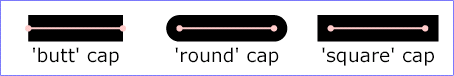
- stroke-linecap: Specifies the shape of the line ends. Legal values are butt, round, and square
- Default value is butt. See illustration below.
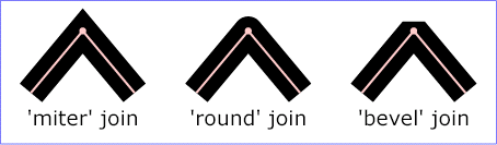
- stroke-linejoin: Specifies the shape of corners of a line. Legal values are miter, bevel and round. Default value is miter. See illustration below.
- stroke-miterlimit: Specifies a limit on the ratio of the miter length to the stroke width in a miter join. If the ratio is exceeded, the join is changed into a bevel join. The default value is 4.
- stroke-dasharray: Specifies a comma-separated list of alternating dash and gap lengths. Makes a solid stroke if omitted.
- stroke-dashoffset: Specifies an offset of the dash pattern at both ends. That is the first and last dash will be shortened by the specified amount.
- stroke-offset: Specifies the offset of a line. Positive values are to he left in the drawing directions, negative to the right.
Stroke-linecap values:
Stroke-linejoin values:
The following attributes applies to text objects (note that text objects may also have stroke styles if stroked)
- font-family: May be serif, sans-serif or monospace. Defaults to "sans-serif"
- font-size: Specifies the size of the font. Defaults to 12.
- font-weight: May be bold or normal. Default is normal
- font-style: May be italic or normal. Default is normal.
- text-decoration: May be none, or underline. Default is none.
Other text attributes, such as text alignment and letter spacing, should be defined at object level.