Power Module
-
There will be mains voltage inside the power module when it is operating. The high voltage wiring is pretty simple, but don't skimp on the insulation/heat shrink on the wires and make sure that all the wires are secure and do not contact anything on the AC/DC power supply.
-
Also note, there are large capacitors on the AC/DC converter, so even after power is removed, there may be high voltage present on the supply for a few minutes. In general, wait a few minutes after unplugging power before you do anything that might involve inadvertently touching the converter.
-
It should also go without saying: Don't do anything inside the power module with high voltage power plugged in.
Attach the wires to the power entry module as shown below.
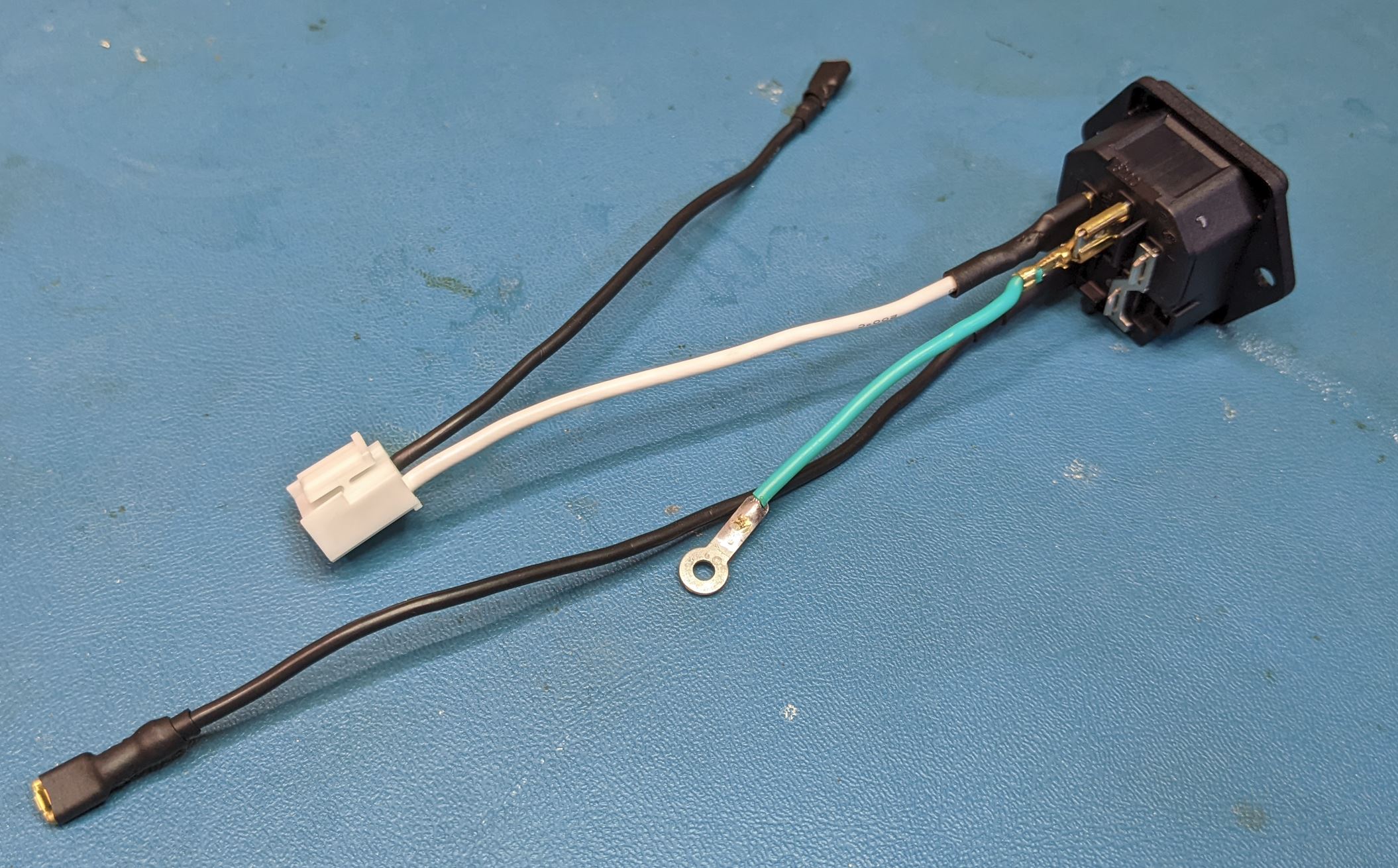
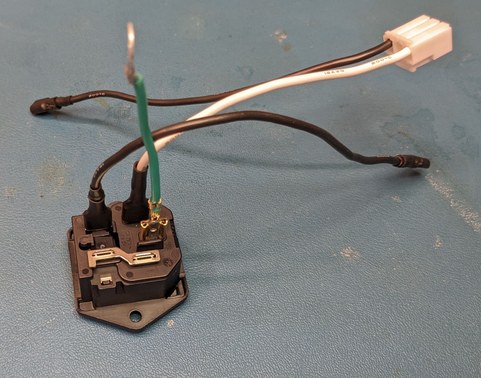
For those unfamiliar with AC wiring, the coloring convention for the wires (in the US, at least) is black for hot (high voltage), white for neutral (return) and green for earth (safety ground).
With the wires attached, slide the power entry module into the back of the power module case and secure with two screws (Self tapping #4 flat head, 3/8" Length).
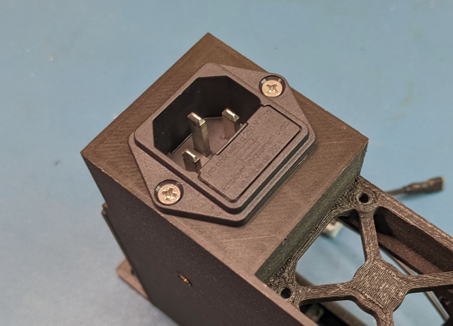
Note that the power entry module can fit in two orientations in the case. Either is okay, but I found the shown orientation worked better for cable routing.
<Fuses?>
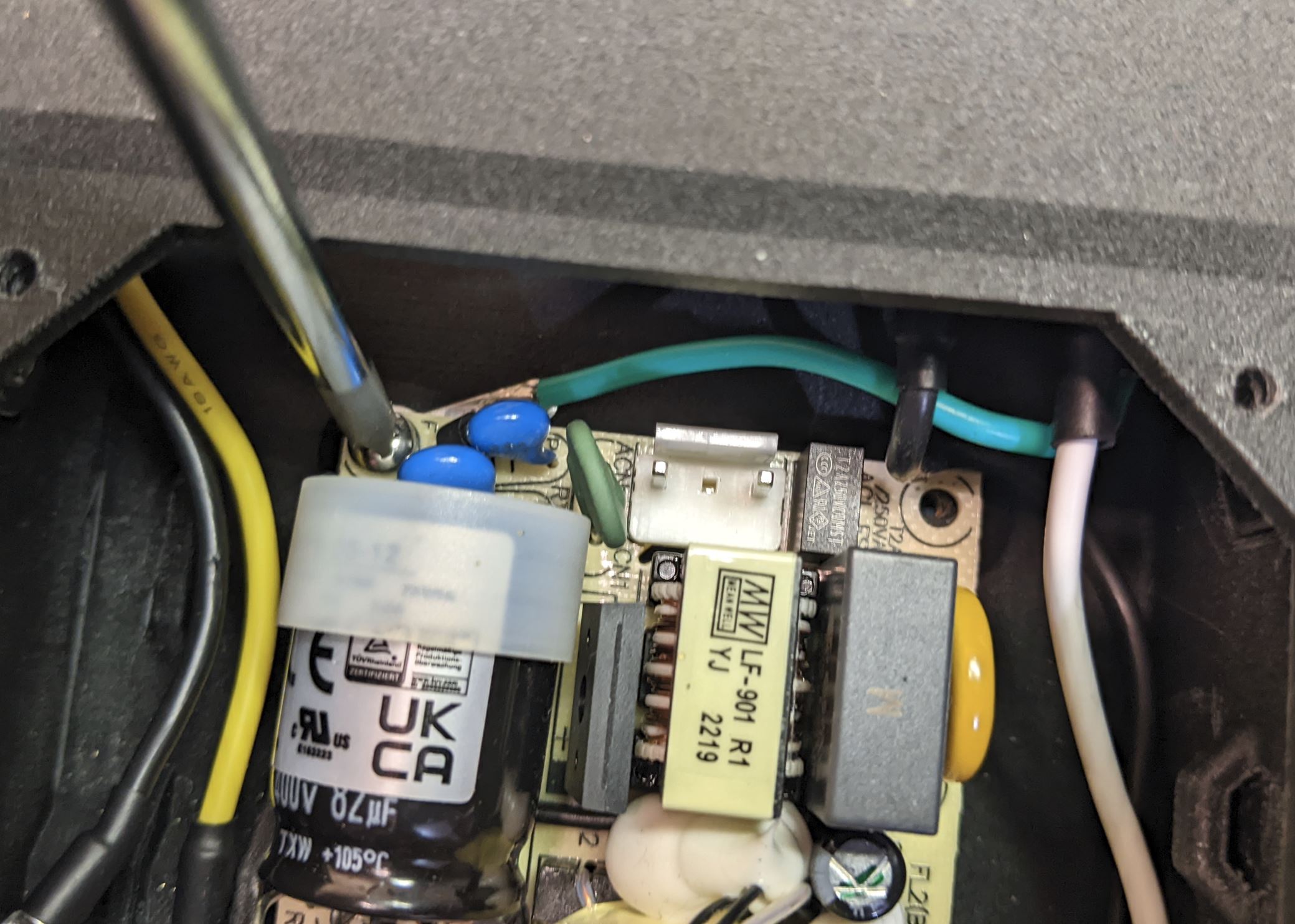
Place the AC/DC converter into the case as shown. The four mounting holes will line up with the four mounting pads in the case. Secure the converter to the case using four #4-40 PHMS (.25" Length). The back left mounting hole also contains contacts for the safety ground. Before installing the screw, slide the safety ground tab between the converter PCB and the pad below it. (This pad is a bit shorter than the rest to account for this).
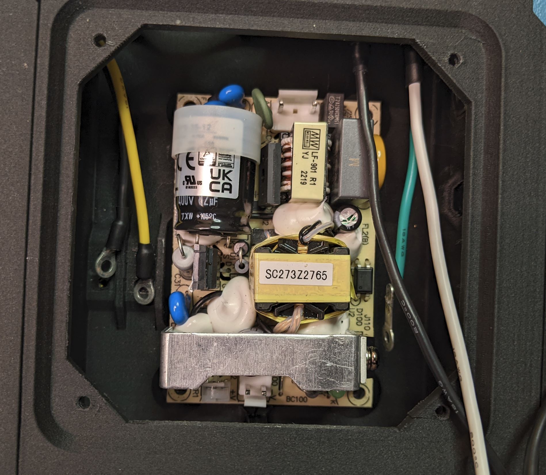
Take note of the two connectors on the board. The AC input connector (the three pin connector with the middle pin missing) should be facing the back of the case.
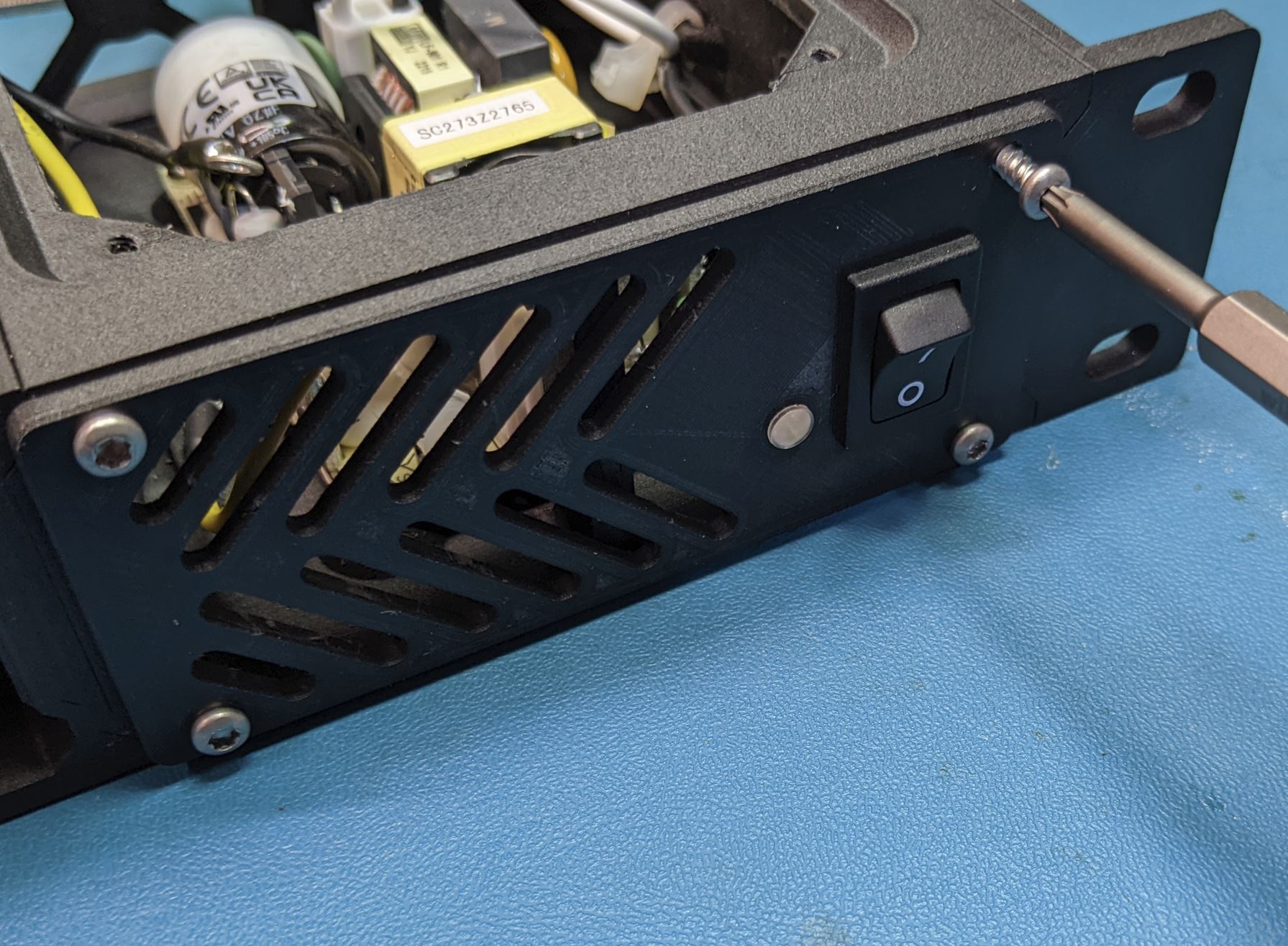
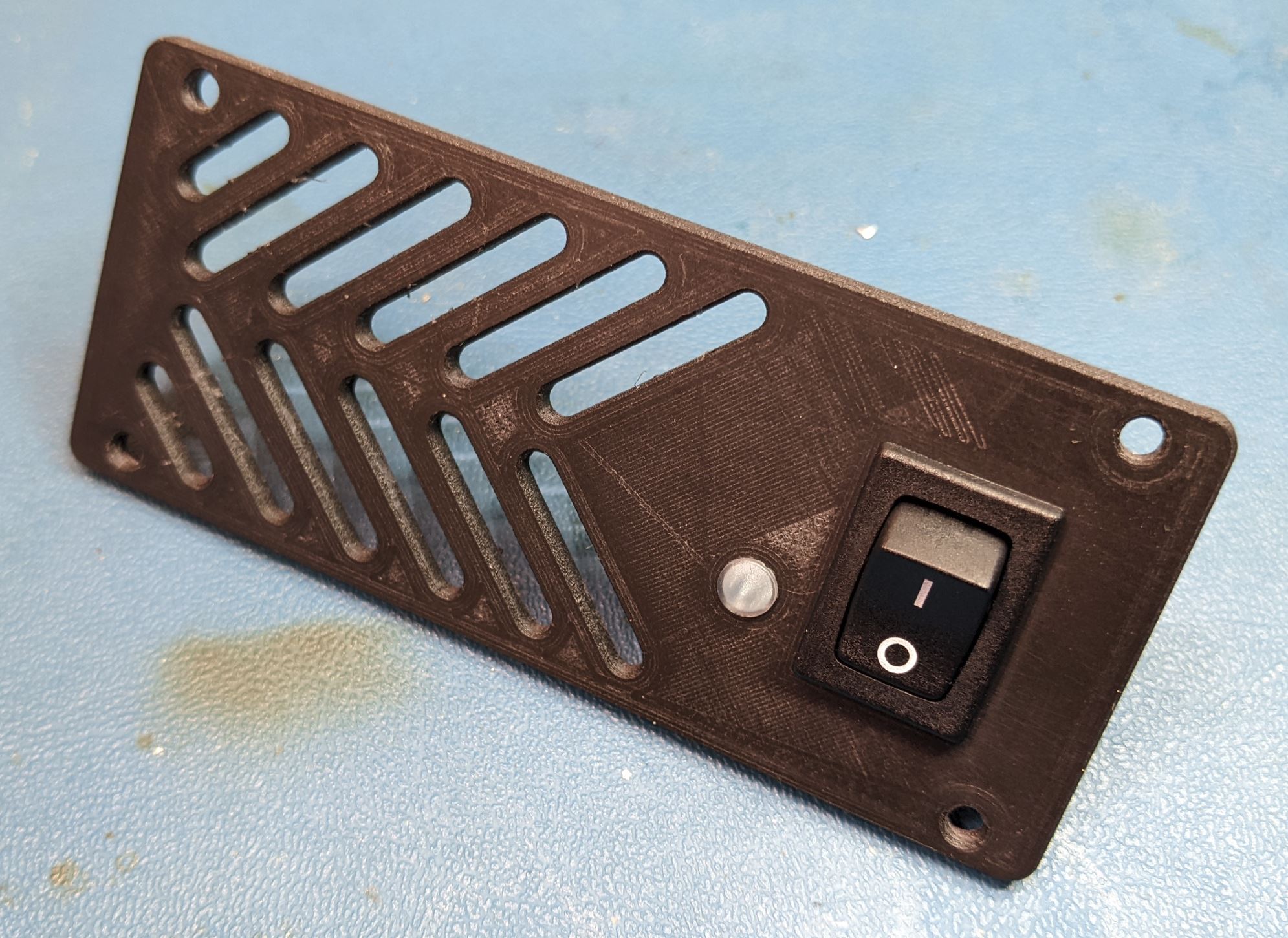
The switch and light pipe both press in from the front side of the front cover as shown. The switch will snap into place, and the light pipe will be a friction fit. You may have to use a knife to widen the hole for the light pipe slightly to make it fit. The small flange on the front of the light pipe should be flush with the front of the cover.
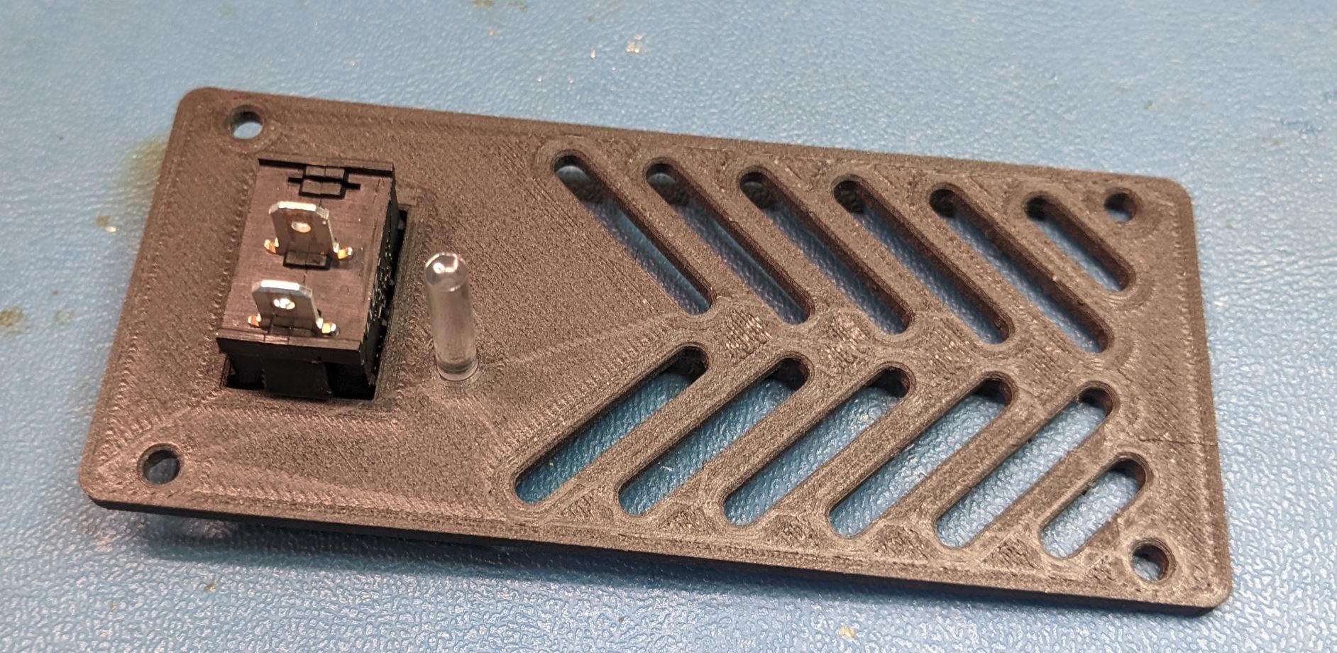
Place the front cover close to its final position and attach the two black wires to the switch. It does not really matter which wire goes to which terminal. Take care at this step to make sure the wires are routed so that they can be separated from the AC/DC converter. You will note in the below image that I routed the hot (black) wire behind the safety ground (green).

After the parts are positioned, screw the front cover to the power module frame with four self tapping pan screws. (#4 size, .5" Length)