Wiring
Wiring can be a deceptively difficult part of projects. Before starting assembly, make the various wire harnesses as shown below. In general, the length of the wires is not super critical. That being said, try to get close to what is shown below. Too much wire and you won't be able to find a place to stuff it, too little and things won't fit.
For most of the wires, I used heatshrink to cover exposed metal. This is more critical on the high voltage wires, but good general practice for all wires.
You don't technically need a crimp tool, but it will help a lot with getting the crimps right. If you don't have one, this one is pretty decent.
You will need a few sizes of wire. I used 18 gage wire for the high voltage and DC transfer wires. I used smaller 24 gage wires for the DC power to the individual device modules. You will want a few different colors of wire.
- 18 gage wire in white, black, yellow, and green.
- 24 gage wire in yellow, black, and some third color (I used blue)
| Connector | Quantity |
|---|---|
| Spade terminals, .25" | - |
| Spade terminals, .18" | - |
| Ring Terminals, #4, flat | - |
| Ring Terminals, #4, crimp | - |
| Connector, 3pin | - |
| Connector, 2pin | - |
| JST-VH Crimp Contacts | - |
The JST VH connectors are sometimes out-of-stock. There are other compatible connectors you can use like the TE 'Economy Power' connectors.
| Wire Name | Description | Wire Length | End 1 | End 2 | Wire Gage | QTY | Notes |
|---|---|---|---|---|---|---|---|
| AC Inlet Hot Wire | 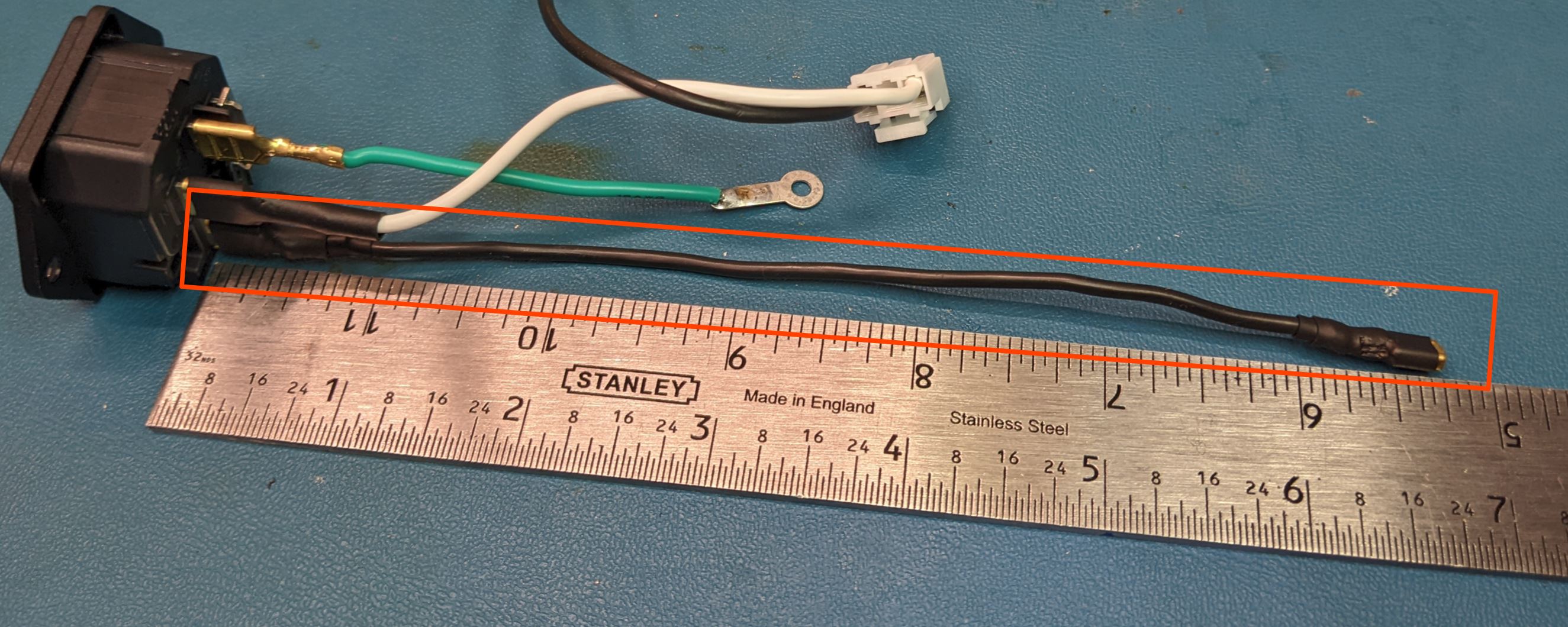 |
6.75 in | Spade Terminal, .25" | Spade Terminal, .187" | 18 | 1 | Cover all exposed metal on the contacts with heat shrink |
| AC Inlet Switch Cable | 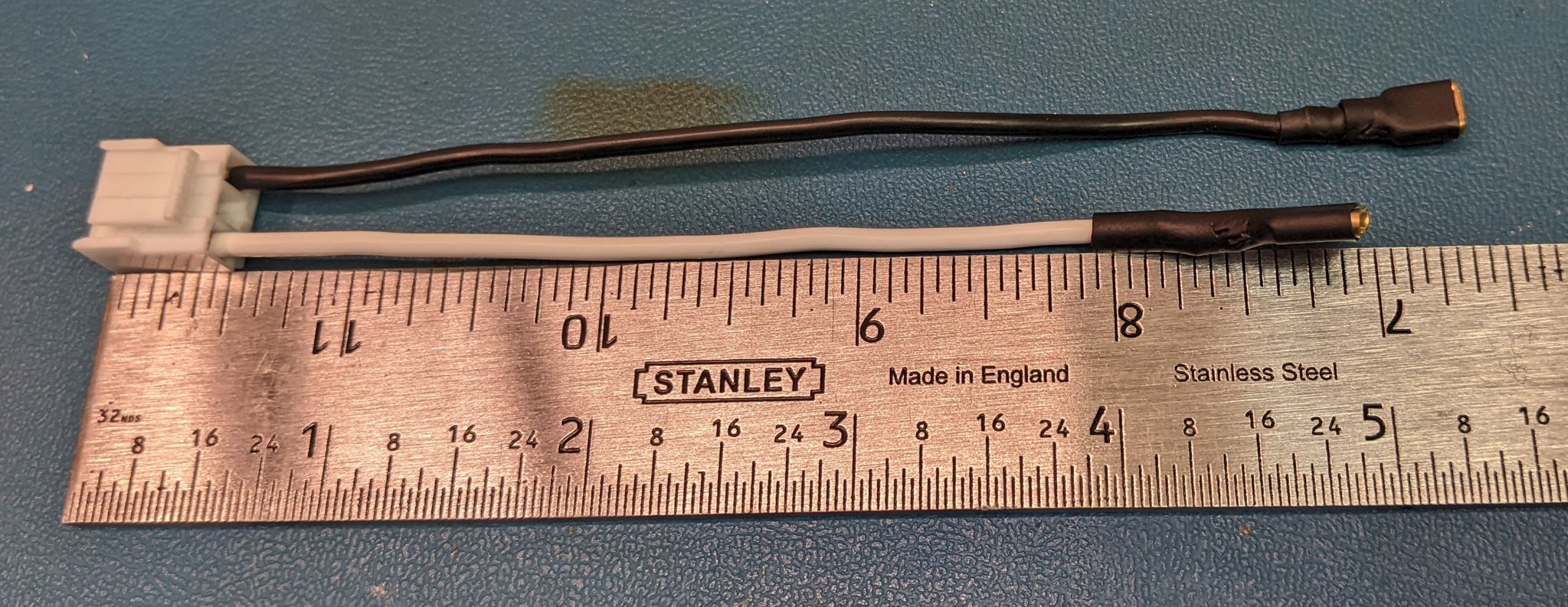 |
5 in | Connector, 3 pin | White: Spade Terminal: .25" Black: Spade Terminal: .187" |
18 | 1 | Cover all exposed metal on the contacts with heat shrink. Make sure to match wire colors to the correct locations in the connector. |
| AC Inlet Earth Wire | 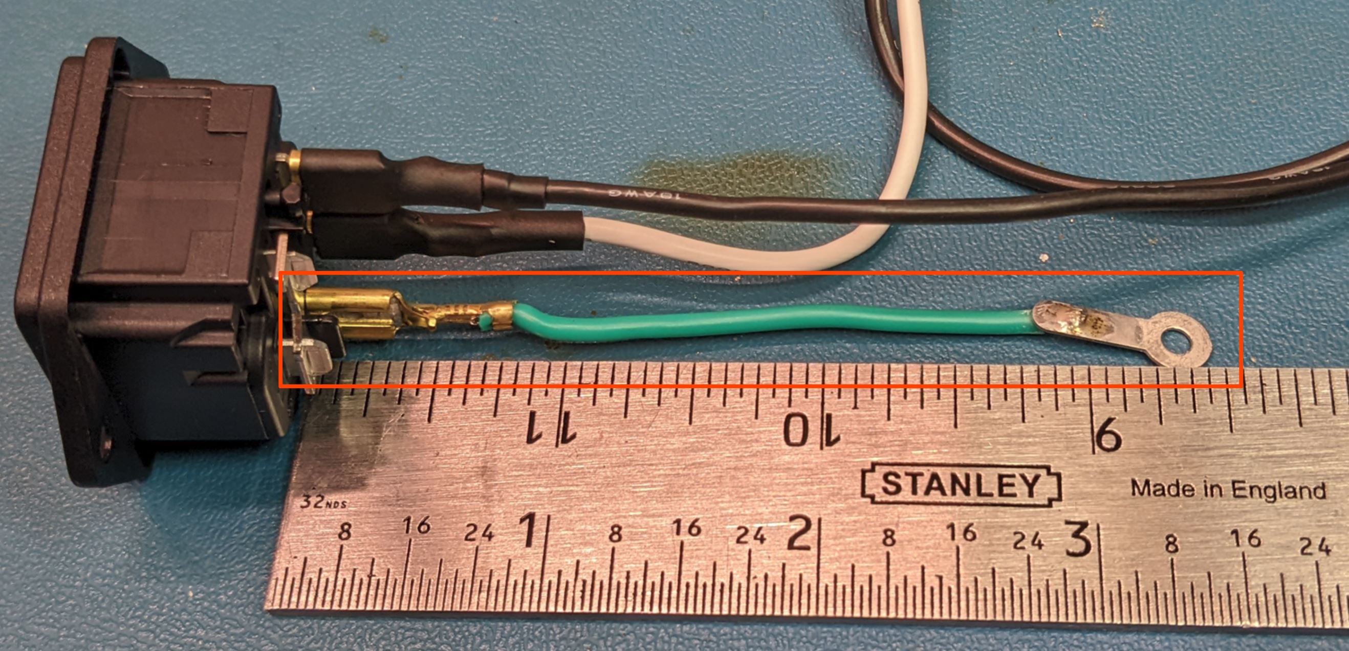 |
3.25in | Spade Terminal, .25" | Ring Terminal, flat | 18 | 1 | Heat shrink optional |
| DC Output Cable | 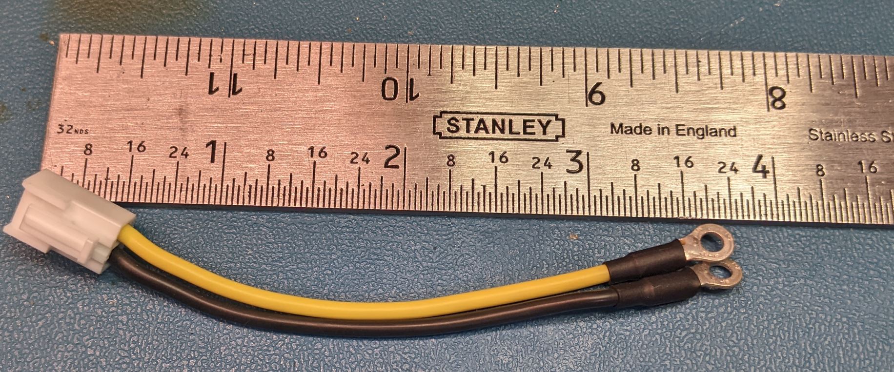 |
3.75in | Connector, 2 pin | Ring Terminal, crimp (2X) | 18 | 1 | Make sure to match wire colors to the correct locations in the connector. |
| Fan | 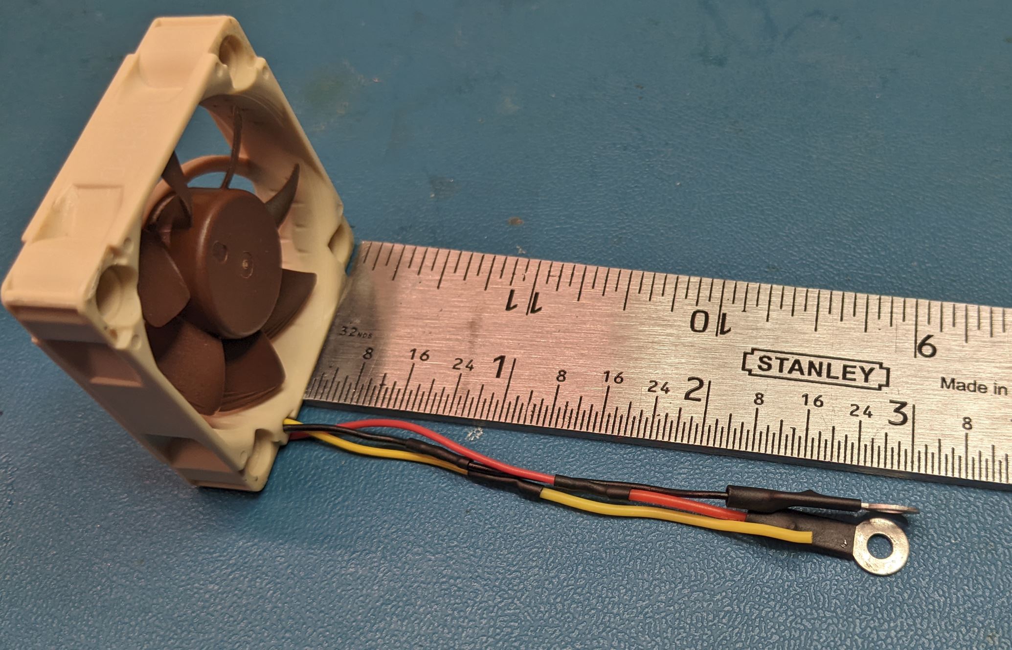 |
3 in | Fan | Ring Terminal, flat (2X) | - | 1 | Make sure to verify the wire colors. You want terminals on the power (generally red or yellow) and ground (generally black). The pictured fan uses red for power and yellow for the tachometer signal. The tachometer signal is unused. |
| DC Transfer Wires, Long | 6.5 in | Ring Terminal, Crimp | Ring Terminal, Crimp | 18 | Yellow: 1X Black: 1X |
- |
| Wire Name | Description | Wire Length | End 1 | End 2 | Wire Gage | QTY | Notes |
|---|---|---|---|---|---|---|---|
| DC Transfer Wires, Short | 5 in | Ring Terminal, Crimp | Ring Terminal, Crimp | 18 | Yellow: 2X Black: 2X |
- | |
| Switch | 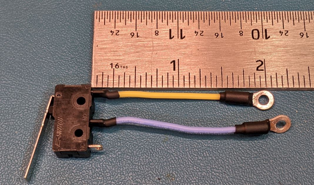 |
2 in | Switch | Ring Terminal, Crimp | 24 | 3 | Make sure to match the wire colors to the NO and C terminals on the switch. There should be no continuity between the two wires when the switch is open. |
| DC Plug | 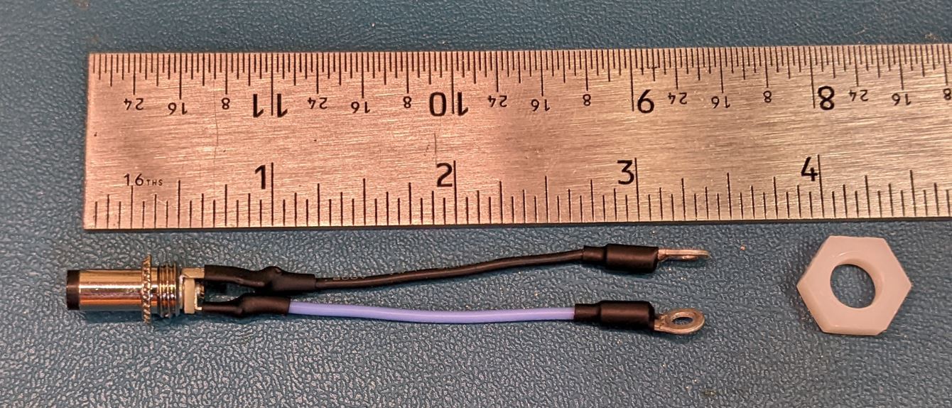 |
2 in | DC plug | Ring Terminal, Crimp | 24 | 3 | Make sure to match the colors to the proper locations on the the DC plug. The yellow should be the center. Trim the metal contacts near the wire holes. If the contacts are too long, it won't fit in the back of the case. |
| Fan | 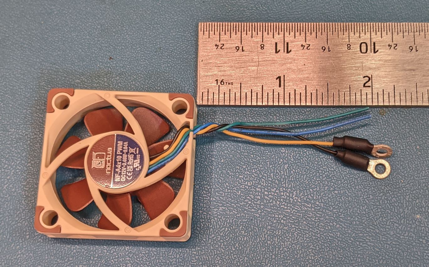 |
2 in | Fan | Ring Terminal, Crimp | - | 3 | Make sure to verify the wire colors. You want terminals on the power (generally red or yellow) and ground (generally black). The pictured fan also has green (tachometer) and blue (PWM). The other wires are unused. |