This project enhances game pieces for a board game. The selected game is checkers and the checker piece will be modified. The modification is to place an RFID chip inside a 3D printed checker piece. When the RFID tag is registered with the Raspberry Pi, the student will provide their content that consist of a audio file and pictures. The details to create the project is described and published on GitHub.
The hardware is an RFID reader connected to a Raspberry Pi. When the RFID reads a know tag, it will signal playback of music with associated images. A 3D part will be created and a known RFID tag will be placed inside of the game piece. When the game piece comes off the board, the player will swipe it across the RFID reader. The student's content will play on a HDMI screen that has a built in speaker.
- Hardware/Software installation for Project
- Development files for picture/audio/RFID
- Student Create Software
- Student 3D Printing
- Testing
- Turn up the volume (via script or before hand).
- Enable the user to set a volume level in their setup.
- Need to add another field to compensate for audio levels.
- Audio levels may not be the same for each student.
- Audio levels need to be set initially for the default audio/pictures.
- All 3D printing aspects are pending.
- Board has 64 squares
- Board dimension: 28" x 28"
- Each player has 12 pieces (Total of 24 pieces)
- Board is made of fabric, previously purchased.

- Dimensions
-
Player Piece is 3" diameter.
-
Thickness is 3/4" in height.
-
- One face will remain standard, the other face will be created by the student (King side).

- Connect primary connections, excluding the power (the USB Power cable).
- Ignore the hardware case, it is not required.
- The RFID hardware is not shown.
- The mouse is not required since the image is headless.
- The HDMI is connected to a HDMI monitor with speakers.
- Turn on the HDMI monitor so that it is reconized when power is turned on.
- The SD card is expected to be previously installed with the described image.

- Connect the RFID hardware.
- This is connected on the far left because the far right is used for the serial connection (if used).

- This is connected on the far left because the far right is used for the serial connection (if used).
- Connect the the power (via the usb cable).
- Powering will cause the hardware to boot from the image written to the SD card.
- A log-in screen will appear on the monitor.

Scripts were written to use and bind the installed software. The user needs to login and start two scripts using the screen command.
- Default credentials
- Username: pi
- Password: raspberry
cd $HOME
screen bash
./readAudio.py
CNTRL-A
d
- Screen 2 (returned after detach command)
cd $HOME
./run-loop.sh
The default screen will display images and music. The screen will be played over and over until the student swipes their configured RFID tag.
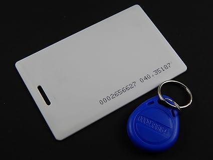
The RFID tag contains a unique number. Before a tag can work, it's RFID number needs to be written into the system with a single audio and multiple pictures.
The following are two example rfid's that came with the purchase of the RFID reader. If their RFID number has already been setup with the Raspberry Pi, then the following will happen.
- A default image and music will play continously.
- Swipe the example RFID tag across the RFID reader.
- The image and music will change from the default.
- Swipe another example RFID tag across the RFID reader.
- The image and music will change again.
- When the music is complete, the default will play again.
- To exit the program, simply hit CNTRL-C.
The Raspberry Pi needs to be shutdown gracefully. This is to avoid corruption of the Image on the SD card. You need to invoke the command as an administrator, therefore, use 'sudo'. You may be prompted for a password. The password is the same as the login password.
- Gracefully shutdown the Pi for power off.
sudo shutdown now -h
- Pull the USB power from the board when the text on the screen stops for a long duration.
The documentation is created using doxygen. This documentation is stored in git hub: https://github.com/jgithubs/jsplayarea Doxygen is used to verify the documentation before it is uploaded to GitHub.
- Create a configuration file
doxygen -g doxyConfig
- Modify the configuration file for github
  Line 035, PROJECT_NAME           = "Checkerboard Project"
  Line 061, OUTPUT_DIRECTORY       = ./DoxyOutput
  Line 793, INPUT                  = README.md \
                                     .
  Line 867, RECURSIVE              = YES
  Line 929, IMAGE_PATH             = .
  Line 985, USE_MDFILE_AS_MAINPAGE = README.md
- Difference between default configuration and modified configuration
gitbash> diff doxyDefault DoxyConfig
35c35
< PROJECT_NAME           = "My Project"
---
> PROJECT_NAME           = "Checkerboard Project"
61c61
< OUTPUT_DIRECTORY       =
---
> OUTPUT_DIRECTORY       = ../DoxyOutput
793c793,794
< INPUT                  =
---
> INPUT                  = README.md \
>                          .
867c868
< RECURSIVE              = NO
---
> RECURSIVE              = YES
929c930
< IMAGE_PATH             =
---
> IMAGE_PATH             = .
985c986
< USE_MDFILE_AS_MAINPAGE =
---
> USE_MDFILE_AS_MAINPAGE = README.md
- Create the output
doxygen doxyConfig
- View the output in the following directory. The output will show up in the default web browser.
../DoxyOutput/html/index.html
- The desired format is Markdown (MD), https://github.com/adam-p/markdown-here/wiki/Markdown-Cheatsheet
- Suggested style, http://www.cirosantilli.com/markdown-style-guide/
- Mix, http://rickfoosusa.blogspot.com/2011/10/howto-use-doxygen-with-github.html
The wiring diagram is done using the Fritizing tool.
- Fritzing download, http://fritzing.org/download/
The documentation is stored in GitHub. GitHub has a series of commands to check changes in and out.