Automatic Cable Tester System — firmware, hardware, and Windows UI for detecting open and short circuits in flat-flex and custom cable assemblies.
This project includes:
- Firmware for Arduino-based controllers (Signal Controller + Main Controller)
- Custom 4-layer PCB design
- C# Windows Forms UI for running tests and visualizing results
- Detects open circuits across specified pin ranges
- Detects short circuits between adjacent and non-adjacent pins
- Supports partial range testing (start pin → end pin)
- Real-time results displayed in UI with color-coded pins:
- Green = pass
- OrangeRed = open
- Red = short
- Timestamped test logs
- Debug/diagnostic utilities for I²C comms and pin state checking
The tester is split into three main parts:
-
Signal Controller (Arduino)
- Drives and clears test signals
- Communicates over I²C
- Handles
RUN_OPEN_TESTandCLEAR_SIG_PINScommands
-
Main Controller (Arduino)
- Coordinates tests with the Signal Controller
- Parses commands from the PC UI over Serial
- Runs open, short, or full test sequences
- Returns structured results in CSV-like format:
pin,5,passed
pin,6,open
pin,7,short,9
done
-
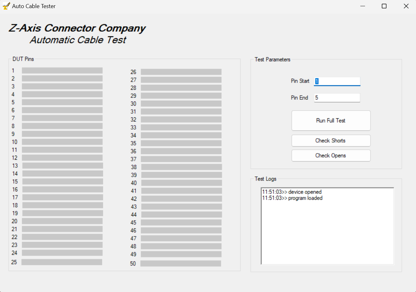
Windows UI (C# WinForms)
- Sends commands to the tester via Serial
- Displays pin states in a visual grid of textboxes
- Provides logs and pass/fail summaries
- Allows running Open, Short, or Full Test
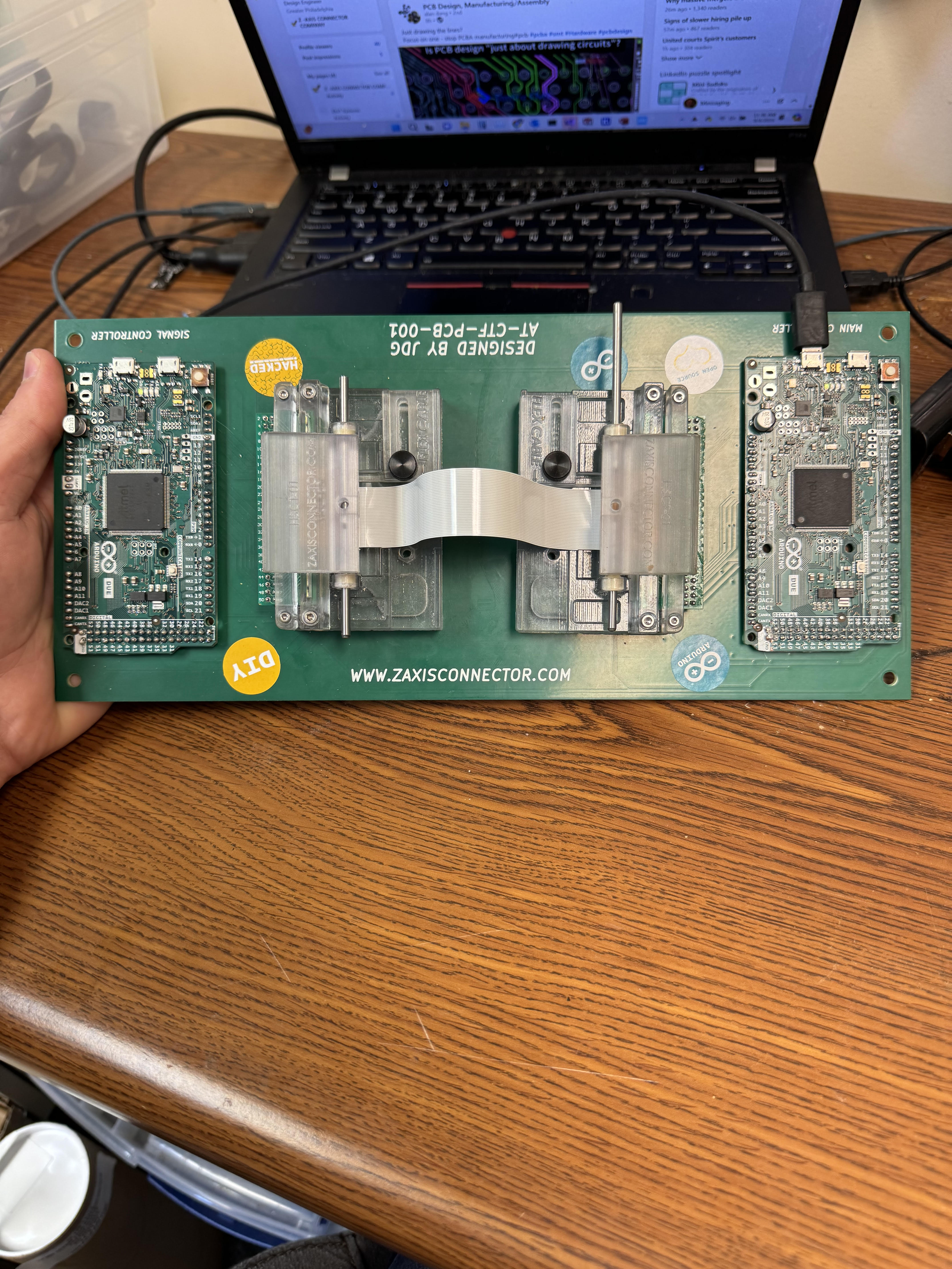
- Custom 4-layer AT-CTF-PCB-001 tester PCB
- Arduino-compatible controllers (I²C + Serial)
- DUT (Device Under Test) cable/fixture
- Arduino IDE (for firmware)
- .NET Framework (WinForms UI)
- Visual Studio (for building UI)
-
Connect Device
- Attach the cable/fixture to the tester board
- Connect the Main Controller via USB
-
Launch UI
- Open the Windows application (
AutoFixtureTester.exe) - Select COM port (defaults to first available)
- Open the Windows application (
-
Run Tests
- Enter start and end pin range (1–50)
- Choose:
- Open Test
- Short Test
- Full Test (runs both sequentially)
- Watch pins light up:
- Gray = not in range
- Green = passed
- OrangeRed = open circuit
- Red = short circuit
-
Review Logs
- Results and errors are logged in the bottom panel
- Failures are summarized in a popup
UI Display:
- Pin 1 → ✅ Green
- Pin 2 → ✅ Green
- Pin 3 → ❌ OrangeRed (open)
- Pin 4 + Pin 7 → ❌ Red (short pair)
John Glatts
Design Engineer @ Z-Axis Connector Company
- PCB, firmware, and UI design
- Embedded systems + industrial automation enthusiast
This project is released under the MIT License.
See LICENSE for details.