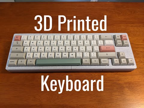
v4n4g0n inspired, 3d printable keyboard


- 3D Printer
- Filament (PLA)
- 1N4148 diodes (one for each switch)
- Switches
- Keycaps
- Stabilizers (6.25u Cherry style for space bar)
- Micro-Controller (I used a Pro Micro with USB C, but others with ATmega32U4 will work)
- Nuts and Bolts (12 3M x 16mm hex screws and nuts)
- Wire (I've had the most luck only using 20-28 awg solid core wire. I use the soldering iron to remove insulation.)
- USB Cable (USB C to USB A in my case)
- Soldering Iron (A basic soldering iron will do, quality does not matter too much)
- Solder (60-40 rosin core solder works best)
- Solder Sucker
- Zip Ties (for securing micro-controller)
- Download the STL files from the releases section.
- Slice the files using your preferred slicer settings. I recommend using:
- a layer height of 0.2mm
- printing at 90% infill
- a brim for better bed adhesion
- supports for bot parts
- Print the following parts:
- V4N_bot_left.stl (fits a wide range of micro-controllers)
- V4N_bot_right.stl
- V4N_top_left.stl
- V4N_top_right.stl
- Place all switches into the top case pieces.
- Put in space key Stabilizer (you'll regret having to de-solder later if you don't do it now)
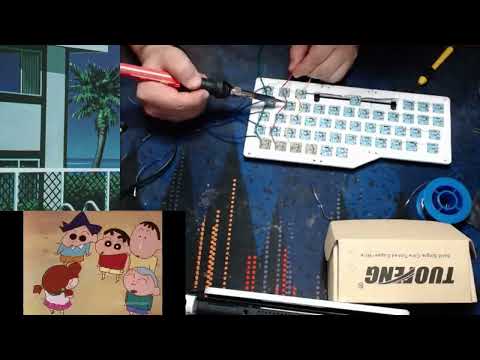
- Solder a diode to each switch, making sure the black side of the diode is facing down. Example image below:

- Solder a wire at the end of each row of switches (this will go to the micro-controller).

- Cut pieces of wire long enough to reach from the top of the switch to the micro-controller pins.
- Solder the wires in the following configuration:
- Tip: I like to burn away the insulation on the wire at the points where I want to solder.

- Tip: I like to burn away the insulation on the wire at the points where I want to solder.

- Solder wires to the micro-controller in the following configuration:


clarification:
the top row (ROW 0) should go to D3 on the Pro Micro, the second row (ROW 1) to D2, continue with the rest of the PINS diagram.
- Download and install QMK Toolbox
- Download the hex file k3yb0rg.hex.
- Connect the micro-controller to your computer.
- Open QMK Toolbox and flash the k3yb0rg.hex file to the micro-controller.
- open hex file
- check "Auto-flash"
- make sure the correct micro-controller is selected (ATmega32U4 for Pro Micro)
- press reset button on micro-controller (if available) or short RST to GND
- wait for "Flash complete!" message
- Your keyboard should now be functional open keyboard tester to verify all keys work: Keyboard Tester
- If you want to customize the keymap or Wiring, you can use keyboard firmware builder, click upload and open the k3yb0rg.json file.
- Place the micro-controller into the bottom left case piece and secure it with a zip tie.
- assemble the top and bottom case pieces together using the 3M x 16mm screws and nuts.
- Place keycaps on switches.
- Enjoy your new keyboard!


you can edit the layers using keyboard firmware builder or QMK Configurator. (Using the k3yb0rg.json file)


Here is an old video guide I made for a previous keyboard: