RAE2822 Airfoil
This tutorial details how to generate a high order 2D mesh of a RAE2822 airfoil with a boundary layer. Case files are provided in the directory Demo/rae2822Airfoil.
First, all meshes generated with MeshOpt will need to reference a CAD geometry in the form of a STEP file. We can take a look at the STEP file by opening it with gmsh: `gmsh rae2822Square.stp'. We will need to set the appropriate boundary conditions for each line in the STEP file. To do this, in the GMSH GUI go to Tools->Options->Geometry and click the box that says 'Line labels'. We will want to use an attractor field for the leading and trailing edges, so we will also need the point labels. We can turn them on by checking the box 'Point labels' in the same menu. If we zoom into the airfoil, we will see something like:
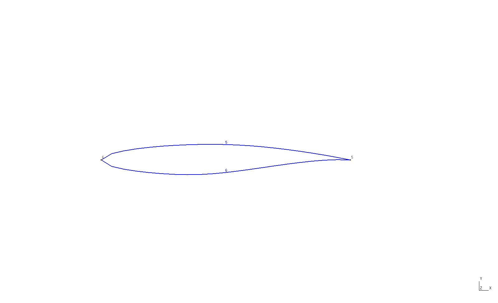
Let's assume we want to run a CFD simulation with this mesh, and want to set the bounding box to a far-field boundary condition and the airfoil surface to a no-slip condition. The far-field boundary will be geometry lines 1-4 and the viscous boundary will be composed of lines 5 and 6. For refinement purposes, we note that the leading and trailing edges are defined by points 5 and 6.
We can now generate a GMSH geometry file; let's call is rae2822.geo. The contents of the file are replicated below.
fflc = 10.0;
surf_len = 0.1;
lete_factor = 0.25;

Geometry.Tolerance = 1.0e-12;
Mesh.CharacteristicLengthMax = fflc;
Mesh.CharacteristicLengthExtendFromBoundary = 1;
Mesh.SaveParametric = 1;
Merge "rae2822Square.stp";

// Set physical tags for boundary conditions
Physical Line(6) = {1:4};
Physical Line(7) = {5,6};


Physical Surface(0) = {1};


Field[1] = Attractor;
Field[1].NodesList = {5,6};


Field[2] = Threshold;
Field[2].IField = 1;
Field[2].LcMin = 0.01;
Field[2].LcMax = 0.05;
Field[2].DistMin = 0.0;
Field[2].DistMax = 0.15;
Field[2].StopAtDistMax = 1;


Field[5] = Box;
Field[5].VOut = fflc;
Field[5].VIn = surf_len;
Field[5].XMax = 5;
Field[5].XMin = -1;
Field[5].YMax = 1.0;
Field[5].YMin = -1.0;
Field[5].ZMax = 1;
Field[5].ZMin = -1;

Field[6] = Box;
Field[6].VOut = fflc;
Field[6].VIn = 5*surf_len;
Field[6].XMax = 25.0;
Field[6].XMin = -5;
Field[6].YMax = 3.0;
Field[6].YMin = -3.0;
Field[6].ZMax = 1;
Field[6].ZMin = -1;


Field[10] = Min;
Field[10].FieldsList = {2,5,6};

Background Field = 10;
We start by defining the far-field and surface mesh size field lengths, fflc and surf_len, respectively. We then set some GMSH parameters, which are detailed in GMSH's user manual. The critical parameter here is Mesh.SaveParametric=1 which tells GMSH to save the parametric coordinates of the nodes.
We then specify the boundary conditions on the edges with the Physical Line() command. Note the line
Physical Surface(0) = {1}. This is very important. For some reason when Mesh.SaveParametric=1, GMSH will not save the mesh elements, only the boundary layer edges/faces. If we set a physical surface (for 2D meshes) or physical volume (for 3D), everything seems to be written out just fine.
Next, we create a threshold field defined by an attractor. The attractor will refine the mesh around the geometric points 5 and 6, which are located at the leading and trailing edges. Several box fields are generated, and finally we take the minimum of fields 2,5, and 6 using the Min field. Lastly we set be background field to be the Min field.
Now it's time to create the mesh:
gmsh -2 rae2822.geo
which creates a mesh named rae2822.msh.
Next we set up a MeshOpt.config file, the contents of which are replicated below.
CaseParameters{
	GMSHFileName = rae2822.msh;
	STEPFileName = rae2822Square.stp;
	OutputFileName = rae2822BL.msh;
}

BLParameters{
	GenerateBL = true;
	Thickness = 0.1;
	NLayers = 5;
	GrowthRatio = 1.5;
        BLSurfID = 7;
}

HighOrderParameters{
	Order = 4;
	TargetMinQuality = 0.9;
	OptimizedNodeSpacing = true;
}
First we create the CaseParameters list which specifies general runtime level parameters. GMSHFileName and STEPFileName are set according to the files we just generated, while we set OutputFileName to the name is set to our desired high order mesh file name.
Next we specify boundary layer parameters. If there will be no boundary layer in the mesh, this section can be omitted. For this example, we would like to generate a boundary layer on boundaries with a physical ID of 7, and we would like MeshOpt to make it (as opposed to GMSH). Therefore, we set GenerateBL = true and BLSurfID = 7. Alternatively, if we wanted to let MeshOpt know that GMSH created a single-layer-thick boundary layer and that MeshOpt should subdivide it, we could set HasBL=true.
We set Thickness = 0.05, which sets the target boundary layer thickness. Note that the actual thickness may differ, and may in fact be significantly less than desired. In these cases, it's best to increase the Thickness parameter and hope for the best.The number of layers is set to five with NLayers = 5 and the boundary layer growth ratio is set to 1.5.
Lastly, we specify the HighOrderParameters list. For this example we set the order to 4 and the target minimum quality to 0.9. This ensures that elements with qualities greater than 0.9 are not optimized, saving resources. Finally we set OptimizedNodeSpacing = true to indicate that we would like to use optimized nodal interpolation.
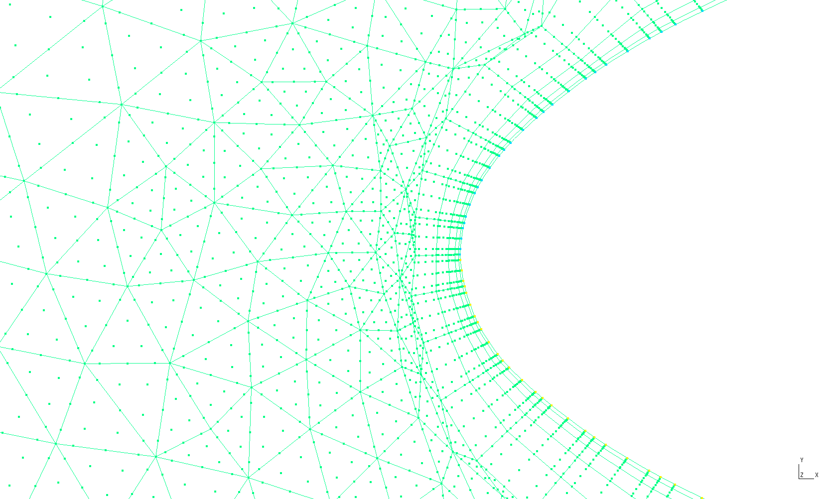
It's finally time to run MeshOpt and generate our high order mesh by running by simply executing the binary in the working directory. After several seconds, MeshOpt should have written out a file named rae2822BL.msh. Below we can see the elements and their nodes near the leading edge: