This is a firmware to use the ESP32 as WiFi NAT router. It can be used as:
- Simple range extender for an existing WiFi network
- Setting up an additional WiFi network with different SSID/password and restricted access for guests or IOT devices
- Convert a corporate (WPA2-Enterprise) network to a regular network, for simple devices
- MCP-server to control your network using agentic AI
- Debugging and monitoring of WiFi devices
- NAT Routing: Full WiFi NAT router with IP forwarding (15+ Mbps throughput)
- DHCP Reservations: Assign fixed IPs to specific MAC addresses
- Port Forwarding: Map external ports to internal devices
- Firewall: Define ACL to restrict or monitor traffic
- PCAP Capture: Live packet capture can be streamed to Wireshark or other network tools
- WPA2-Enterprise Support: Connect to corporate networks (PEAP, TTLS, TLS) and convert them to WPA2-PSK
- Web Interface: Web UI with password protection for easy configuration
- Serial Console: Full CLI for advanced configuration
- Remote Console: Network-accessible CLI via TCP (password protected)
- Connected Clients Display: View all connected devices with MAC, IP, and device names
- Static IP Support: Configure static IP for the STA (upstream) interface
- LED Status Indicator: Visual feedback for connection and traffic status
- OLED Display: Status display on 72x40 I2C SSD1306 OLEDs (as found on some ESP32-C3 mini boards)
- TTL Override: Set a fixed TTL for upstream packets (useful for hiding NAT from ISPs)
- MCP Bridge (AI-Ready): BETA - Control the router from AI assistants (Claude, etc.) via the Model Context Protocol
The maximum number of simultaniously connected WiFi clients is 8 (5 on the ESP32c3) due to RAM limitations.
The code is originally based on the Console Component and the esp-idf-nat-example.
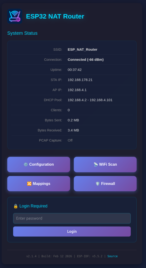
After first boot the ESP32 NAT Router will offer a WiFi network with an open AP and the ssid "ESP32_NAT_Router". Configuration can either be done via a web interface or via the serial console.
The web interface allows for the configuration of all parameters. Connect your PC or smartphone to the WiFi SSID "ESP32_NAT_Router" and point your browser to "http://192.168.4.1" (or later the configured AP IP address).
The web interface consists of five pages:
The main dashboard displays:
- Current connection status and uptime
- STA (upstream) and AP IP addresses and MAC addresses
- Used IP pool for DHCP
- Number of connected clients
- Bytes sent and received
- PCAP capture status (when enabled: captured/dropped packet counts)
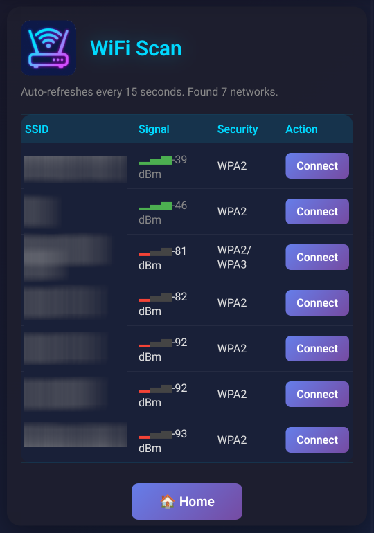
Shows a WiFi network scan and allows for direct connection via the config page.
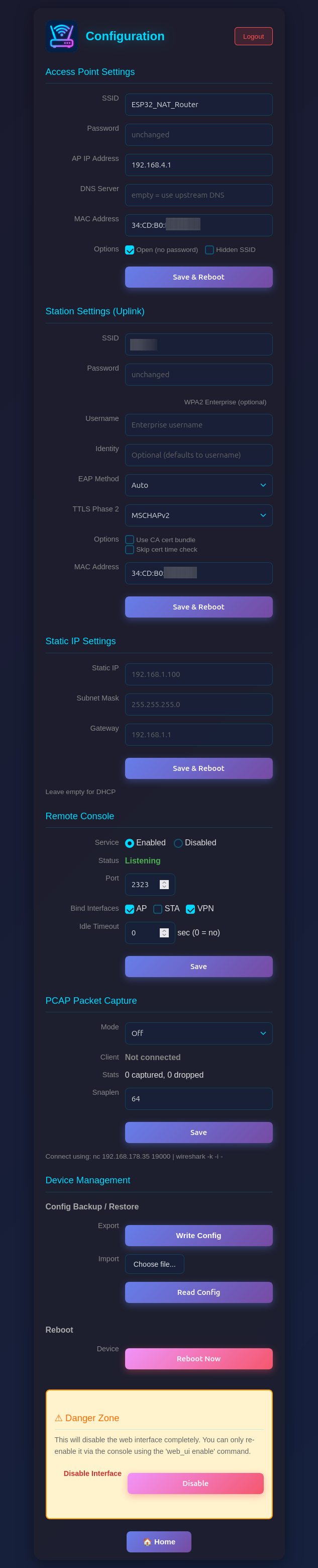
Configure all router settings:
- Access Point Settings: Configure the ESP32's access point name, password, IP address (default: 192.168.4.1), DNS server, and MAC address
- Station Settings (Uplink): Enter the SSID and password for the upstream WiFi network (leave password blank for open networks), with optional WPA2-Enterprise settings (EAP method, TTLS Phase 2, CA cert bundle, time check) and MAC address customization
- Static IP Settings: Optionally configure a static IP for the STA (upstream) interface
- PCAP Packet Capture: Enable/disable packet capture and configure snaplen (max bytes per packet)
- Device Management: Config backup/restore, reboot, and danger zone (disable web interface)
- Click "Apply", "Connect", or "Set Static IP" to apply changes (the ESP32 will reboot)
Be aware that changes to AP settings (including the AP IP address) also affect the config interface itself - after changing the AP IP address, reconnect to the ESP32 at the new IP address to continue configuration. Also all currently defined DHCP reservations and port forwards will be deleted.
The Configuration page includes a Config Backup / Restore section under Device Management:
- Export (Write Config): Downloads a JSON file containing all router settings (WiFi credentials, DHCP reservations, port mappings, ACL rules, etc.)
- Import (Read Config): Upload a previously exported JSON file to restore settings. The device reboots automatically after import to apply the configuration.
This is useful for cloning settings across multiple devices or for backup before a factory reset.
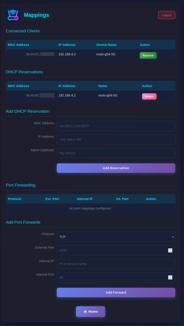
Manage network mappings:
- Connected Clients: Shows all currently connected clients with MAC, IP, and optially name.
- DHCP Reservations: Assign fixed IP addresses to specific MAC addresses (useful for servers/devices that need consistent IPs). Make sure you assign port numbers in the range of the DHCP pool.
- Port Forwarding: Create port mappings to access devices behind the NAT router (e.g.,
TCP 8080 -> 192.168.4.2:80)
Configure Access Control Lists (ACLs) for packet filtering:
- Four ACL Lists: Control traffic in each direction (to_sta, from_sta, to_ap, from_ap)
- Rule Management: Add rules with protocol, source/destination IP, ports, and action (allow/deny)
- Device Names: Use device names from DHCP reservations instead of IP addresses for single-host rules
- Monitoring: Enable packet capture for specific rules with the Monitor flag
- Statistics: View hit counters for each rule and overall ACL statistics
The web interface is visible on both interfaces (AP and STA) and allows configuration access to all parameters. Two security mechanisms are available:
You can protect the /config and /mappings pages with a password. The main status page (/) remains accessible but will show a login form.
Setting a Password (Web Interface):
- On the main page (
/), scroll to the "Set Password" section - Enter and confirm your new password
- Click "Set Password"
- The page will reload and show a login form
Setting a Password (Serial Console):
set_router_password mypassword
To disable password protection, set an empty password:
set_router_password ""
When password protection is enabled:
- The main page shows system status and a login form
- After successful login, you can access
/configand/mappings - Sessions expire after 30 minutes of inactivity
- A "Logout" button appears on all pages when logged in
For maximum security in open environments, you can completely disable the web interface:
From the Web Interface:
- Navigate to the
/configpage - Scroll to the "Danger Zone" section at the bottom
- Click "Disable" button
- Confirm the warning dialog
- The device will reboot with the web interface disabled
From the Serial Console:
web_ui disable
After disabling, the web interface will be completely inaccessible. Re-enable it via the serial console with:
web_ui enable
If you made a mistake and have lost all contact with the ESP you can still use the serial console to reconfigure it. All parameter settings are stored in NVS (non volatile storage), which is not erased by simple re-flashing the binaries. If you want to wipe it out, use "esptool.py -p /dev/ttyUSB0 erase_flash".
If you want to access a device behind the esp32 NAT router: PC -> local router -> esp32NAT -> server
To ensure devices behind the router always get the same IP address, you can configure DHCP reservations:
dhcp_reserve add AA:BB:CC:DD:EE:FF 192.168.4.10 -n MyServer
                                                    ↑ optional friendly name
                                   ↑ reserved IP address
                 ↑ device MAC address
This is useful for servers or IoT devices that other devices need to connect to reliably.
Let's say "server" is exposing a webserver on port 80 and you want to access that from your PC outside the NAT network.
For that you need to configure a port mapping (via the web interface at /mappings or the serial console):
portmap add TCP 8080 192.168.4.2 80
                                 ↑ port of the webserver
                            ↑ server's ip in esp32NAT network
                  ↑ exposed port in the local router's network
Assuming the esp32NAT's IP address in your local router is 192.168.0.57, you can access the server by typing 192.168.0.57:8080 into your browser.
Tip: When you assign a name to a DHCP reservation, you can use that name instead of the IP address when creating firewall (ACL) rules. For example, after creating a reservation with -n MyPhone, you can use MyPhone as source or destination in ACL rules.
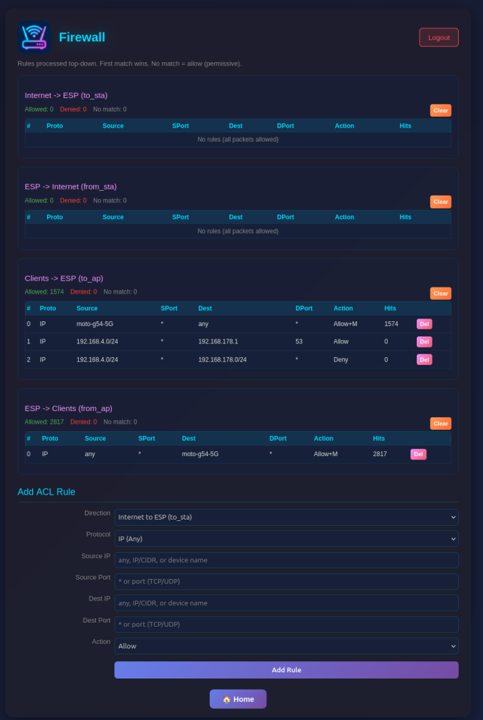
The router includes a stateless packet filtering firewall with four Access Control Lists (ACLs), one for each traffic direction.
                              ESP32 NAT Router
                        ┌───────────────────────┐
                        │                       │
   Internet ◄──────────►│  STA            AP    │◄──────────► Internal
  (Upstream)            │  Interface  Interface │              Clients
                        │                       │
                        └───────────────────────┘
ACLs are named from the perspective of each interface - "to" means traffic arriving at the interface, "from" means traffic leaving the interface:
                              ESP32
                        ┌───────────────────────┐
                        │                       │
   Internet ──to_sta───►│  STA            AP    │◄───to_ap─── Clients
            ◄──from_sta─│                       │───from_ap──►
                        │                       │
                        └───────────────────────┘
| ACL | Interface | Direction | Description |
|---|---|---|---|
| to_sta | STA | Inbound | Internet → ESP32 (traffic arriving at STA interface) |
| from_sta | STA | Outbound | ESP32 → Internet (traffic leaving STA interface) |
| to_ap | AP | Inbound | Clients → ESP32 (traffic arriving at AP interface) |
| from_ap | AP | Outbound | ESP32 → Clients (traffic leaving AP interface) |
- to_sta: Block unwanted incoming traffic from the Internet
- from_sta: Control what internal clients can access on the Internet
- to_ap: Filter traffic from specific internal clients
- from_ap: Control what traffic reaches internal clients
Access the firewall configuration at /firewall. For each ACL you can:
- Add rules with source/destination IP (CIDR notation), protocol, ports, and action
- Use device names from DHCP reservations instead of IP addresses (for single-host /32 rules)
- Enable monitoring to capture matching packets to PCAP
- View hit counters and statistics (device names shown for /32 addresses with reservations)
- Delete individual rules or clear entire lists
acl show [<list>]                    # Show rules and stats
acl add <list> <proto> <src> <sport> <dst> <dport> <action>
acl del <list> <index>               # Delete rule by index
acl clear <list>                     # Clear all rules
Address formats:
any- matches any IP address192.168.4.0/24- CIDR notation (network/mask)192.168.4.100- single host (equivalent to /32)MyPhone- device name from DHCP reservations (resolved to /32)
When displaying rules, device names are shown instead of IP addresses for /32 rules that have a matching DHCP reservation with a name.
Examples:
# Block incoming traffic from a specific IP
acl add to_sta IP 203.0.113.50 * any * deny

# Block a specific device by name (from DHCP reservation)
acl add from_ap IP any * MyPhone * deny

# Allow only DNS and HTTP/HTTPS from clients to Internet
acl add to_ap UDP any * any 53 allow
acl add to_ap TCP any * any 80 allow
acl add to_ap TCP any * any 443 allow
acl add from_sta IP any * any * deny
- Rules are evaluated in order (first match wins)
- If no rule matches, the packet is allowed (permissive default)
- Non-IPv4 traffic (ARP, IPv6) passes through without filtering
- Port filters only apply to TCP/UDP packets; rules with port filters won't match ICMP or other protocols
- Rules persist in NVS storage
Each rule can have one of four actions:
| Action | Packet | Captured to PCAP |
|---|---|---|
allow |
✅ Allowed | ❌ No |
deny |
❌ Dropped | ❌ No |
allow_monitor |
✅ Allowed | ✅ Yes (in ACL mode) |
deny_monitor |
❌ Dropped | ✅ Yes (in ACL mode, before drop) |
The router includes a built-in packet capture feature that streams traffic to Wireshark or other network tools in real-time via TCP.
The capture system supports three modes:
| Mode | Description | STA Traffic | AP Traffic |
|---|---|---|---|
| off | Capture disabled | ❌ | ❌ |
| acl | ACL Monitor mode - only capture packets matching ACL rules with +M flag |
✅ (if flagged) | ✅ (if flagged) |
| promisc | Promiscuous mode - capture all AP client traffic | ❌ | ✅ All |
Key behavior:
- Packets are only buffered when a Wireshark client is connected (saves resources)
- In ACL monitor mode (
pcap mode acl): Only packets matching rules with+M(monitor) flag are captured, from any interface - In promiscuous mode (
pcap mode promisc): All AP traffic is captured; STA traffic is only captured if it matches an ACL+Mrule
The STA interface is intentionally excluded from promiscuous capture to avoid a feedback loop - the PCAP stream itself is sent over the STA interface to Wireshark.
Use cases for monitor rules:
# Capture all DNS queries going to the Internet (for debugging)
acl add from_sta UDP any * any 53 allow_monitor

# Capture specific client's traffic without blocking (by IP)
acl add to_ap IP 192.168.4.100 * any * allow_monitor

# Capture specific client's traffic using device name
acl add to_ap IP MyPhone * any * allow_monitor
-
Set capture mode via the web interface (
/configpage) or serial console: -
Connect Wireshark from your computer:
nc <ESP32's IP address> | wireshark -k -i -Or configure Wireshark directly:
- Go to Capture > Options > Manage Interfaces > Pipes
- Add new pipe:
TCP@<ESP32's IP address>:19000
Other options would be e.g. analyzing the traffic with a tool like zeek:
mkdir zeek_logs && chmod 777 zeek_logs
nc <ESP32's IP address> 19000 | docker run --rm -i -v $(pwd)/zeek_logs:/logs -w /logs zeek/zeek:latest zeek -r -On the Configuration page (/config), the PCAP Packet Capture section allows you to:
- Select capture mode (Off / ACL Monitor / Promiscuous)
- View client connection status
- See captured/dropped packet counts
- Set the snaplen value (64-1600 bytes)
The System Status page (/) shows the current capture mode and statistics.
pcap mode            # Show current capture mode
pcap mode off        # Disable capture
pcap mode acl        # ACL monitor mode (only +M flagged packets)
pcap mode promisc    # Promiscuous mode (all AP traffic)
pcap status          # Show capture statistics
pcap snaplen         # Show current snaplen (bytes per packet)
pcap snaplen 1500    # Set snaplen (64-1600 bytes)
pcap start           # Legacy: enable promiscuous mode
pcap stop            # Legacy: disable capture
- TCP Port: 19000
- Buffer Size: 32KB ring buffer (16 KB on the ESP32c3)
- Default Snaplen: 96 bytes (64 bytes on the ESP32c3, configurable 64-1600)
- Format: Standard PCAP with DLT_EN10MB (Ethernet)
- Single Client: One Wireshark connection at a time
- Use promiscuous mode to capture all traffic from WiFi clients
- Use ACL monitor mode to selectively capture specific traffic (e.g., DNS queries, specific hosts)
- Use a smaller snaplen (e.g., 128) to capture more packets in the buffer if you only need headers
- Use a larger snaplen (e.g., 1500) to capture full packet contents
- Check
pcap statusto monitor for dropped packets (buffer overflow) - No packets are buffered until Wireshark connects, saving CPU and memory
The on-board LED provides visual feedback about connection and traffic status:
- LED off: ESP32 is not connected to upstream AP
- LED on (steady): ESP32 is connected to upstream, no traffic
- LED flickering: ESP32 is connected, traffic is flowing through the router. The flickering intensity is proportional to the traffic volume — heavier traffic produces more intense flickering
By default, the LED is disabled. To enable it, configure the GPIO pin for your board:
set_led_gpio 2          # Set LED to GPIO 2
set_led_gpio none       # Disable LED (default)
set_led_gpio            # Show current setting
Changes take effect after restart.
| Board / Chip | Default LED GPIO |
|---|---|
| ESP32 DevKit v1 / WROOM | GPIO 2 |
| ESP32-S2 | GPIO 2 (varies) |
| ESP32-S3 DevKitC | GPIO 48 (RGB) |
| ESP32-C3 DevKitM / SuperMini | GPIO 8 |
| ESP32-C6 DevKitC | GPIO 8 |
| NodeMCU-32S | GPIO 2 |
| Lolin D32 | GPIO 5 |
| Lolin32 Lite | GPIO 22 |
Note: Some boards have active-low LEDs. ESP32-S3 often uses GPIO 48 for an addressable RGB LED (WS2812) which may require different handling.
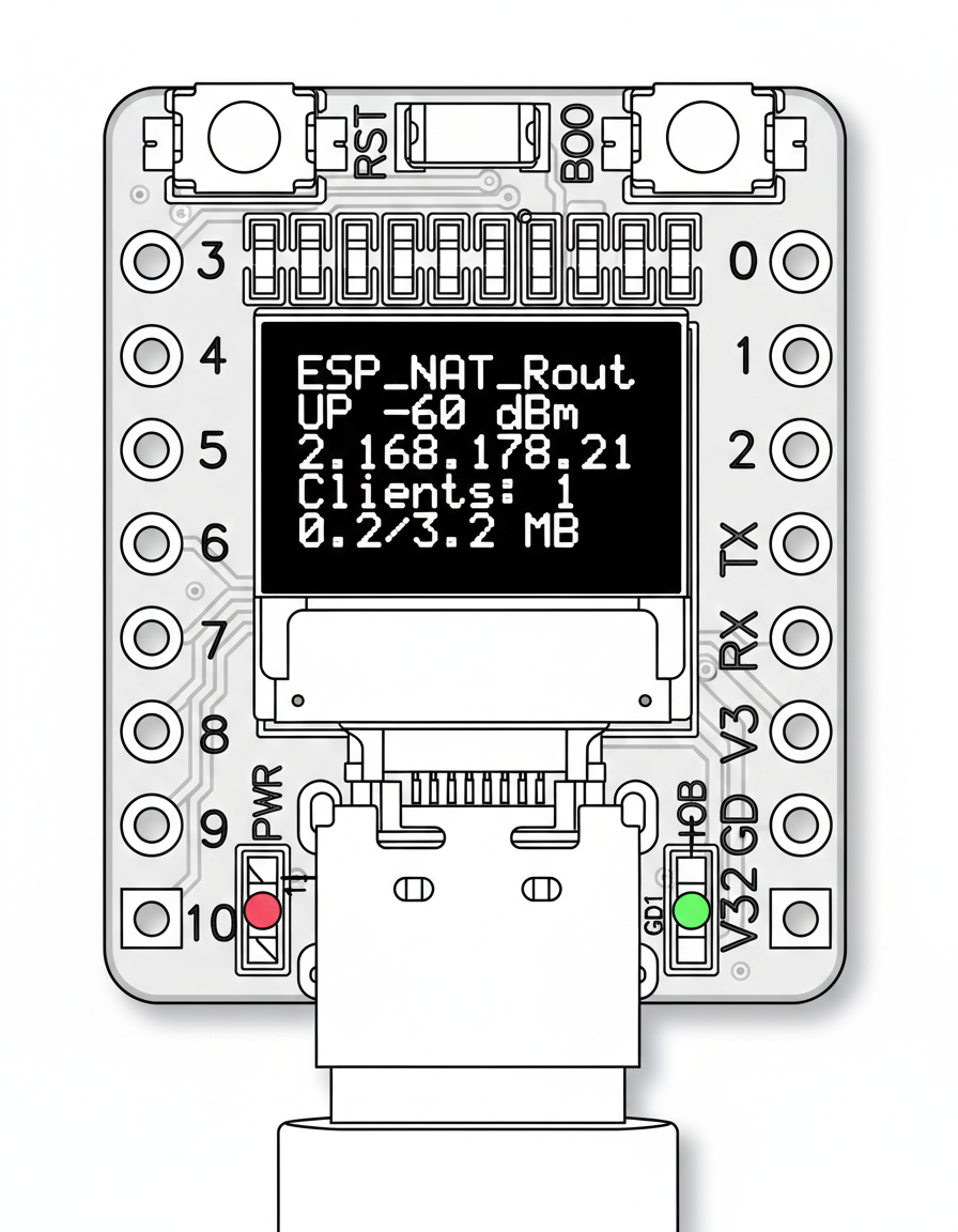
The firmware supports a 72x40 pixel (0.42") SSD1306 OLED display over I2C. This is specifically designed for the small I2C OLEDs found on certain ESP32-C3 mini boards. Other display sizes or drivers are not supported.
The display shows:
- AP SSID
- STA connection status and RSSI
- STA IP address
- Number of connected clients
- Sent/received traffic in MB
The OLED display is disabled by default. Enable and configure it via the serial console:
oled enable              # Enable OLED display (requires reboot)
oled disable             # Disable OLED display (requires reboot)
oled gpio <sda> <scl>    # Set I2C pins (default: SDA=5, SCL=6)
oled status              # Show current configuration
The default I2C pins (SDA=5, SCL=6) match the typical wiring on ESP32-C3 mini boards with built-in OLED.
You can factory reset the ESP32 NAT Router by holding the BOOT button for 5 seconds. This erases all settings stored in NVS (WiFi credentials, port mappings, DHCP reservations, ACL rules, passwords, etc.) and restarts the device with default configuration.
The BOOT button GPIO is selected automatically at compile time based on the chip:
| Chip | BOOT Button GPIO |
|---|---|
| ESP32, ESP32-S2, ESP32-S3 | GPIO 0 |
| ESP32-C3, ESP32-C2, ESP32-C6 | GPIO 9 |
- Press and hold the BOOT button on your ESP32 board
- If an LED is configured, it will rapidly blink to indicate the button press is being detected
- Continue holding for 5 seconds
- The device will erase all settings and restart automatically
After reset, the ESP32 will boot with default settings (open AP with SSID "ESP32_NAT_Router").
- Serial console: Use the
factory_resetcommand - Full flash erase:
esptool.py -p /dev/ttyUSB0 erase_flash(also erases firmware)
The router can override the TTL (Time To Live) value in the IP header for all packets sent upstream via the STA interface. This can be useful to:
- Hide the presence of a NAT router from ISPs that detect multiple devices via TTL variations
- Ensure consistent TTL values for all outgoing traffic
set_ttl 64          # Set TTL to 64 for all upstream packets
set_ttl 0           # Disable TTL override (default, no change)
set_ttl             # Show current setting
The setting is stored in NVS and takes effect immediately (no restart required).
Note: TTL override only affects packets going to the upstream network (via STA interface). It does not affect traffic between the ESP32 and its connected clients.
Hidden SSID
The AP can be configured to hide its SSID from network scans. When enabled, clients must know the exact SSID to connect.
set_ap_hidden on        # Hide the AP SSID
set_ap_hidden off       # Show the AP SSID (default)
set_ap_hidden           # Show current setting
Changes require a restart to take effect.
Note: Hiding the SSID provides minimal security benefit. The SSID is still transmitted in probe responses and association frames. Use strong WPA2 passwords for actual security.
The router supports connecting to WPA2-Enterprise (802.1X) networks, commonly used in corporate and university environments. This allows the ESP32 to bridge an enterprise network to a standard WPA2-PSK access point.
| Value | Method | Description |
|---|---|---|
| 0 | Auto | Automatic detection (default) |
| 1 | PEAP | Protected EAP (most common in corporate networks) |
| 2 | TTLS | Tunneled TLS |
| 3 | TLS | Certificate-based TLS |
| Value | Method |
|---|---|
| 0 | MSCHAPv2 (default) |
| 1 | MSCHAP |
| 2 | PAP |
| 3 | CHAP |
Web Interface: On the /config page, the Station Settings section includes fields for Enterprise username, identity, EAP method, TTLS Phase 2, and options for CA cert bundle and certificate time check.
Serial Console:
set_sta MyCorpWiFi mypassword -u john.doe -a anonymous -e 1 -p 0 -c 1 -t 1
| Flag | Description |
|---|---|
-u |
Enterprise username |
-a |
Enterprise identity (defaults to username if omitted) |
-e |
EAP method (0=Auto, 1=PEAP, 2=TTLS, 3=TLS) |
-p |
TTLS Phase 2 (0=MSCHAPv2, 1=MSCHAP, 2=PAP, 3=CHAP) |
-c 1 |
Enable CA certificate bundle for server validation |
-t 1 |
Skip certificate time check (useful if device has no RTC) |
All settings are persisted in NVS and applied on next connection.
The router provides a network-accessible CLI via TCP, allowing remote configuration without physical serial access.
- TCP Connection: Connect via port 2323 (configurable)
- Password Protected: Uses the same password as the web interface
- Full CLI Access: All serial console commands available remotely
- Single Session: Only one remote session at a time
- Idle Timeout: Automatic disconnect after inactivity (default: 5 minutes)
- Disabled by Default: Must be explicitly enabled for security
The remote console currently uses plain TCP (unencrypted). Only use on trusted networks. Do not expose port 2323 to the internet.
First, set a web password (recommended):
set_router_password mypassword
Then enable the remote console:
remote_console enable
From any computer on the network:
nc 192.168.4.1 2323Or using telnet:
telnet 192.168.4.1 2323You'll be prompted for the password. After authentication, you get full CLI access.
remote_console status              # Show remote console status
remote_console enable              # Enable remote console
remote_console disable             # Disable remote console
remote_console port <port>         # Set TCP port (default: 2323)
remote_console bind <both|ap|sta>  # Set interface binding
remote_console timeout <seconds>   # Set idle timeout (0 = no timeout)
remote_console kick                # Disconnect current session
| Setting | Default | Description |
|---|---|---|
| Port | 2323 | TCP port for connections |
| Bind | AP only | Which interface(s) to listen on |
| Timeout | 300 sec | Idle timeout before disconnect |
| Enabled | No | Service must be explicitly enabled |
- Use
quitorexitto disconnect gracefully - Press Ctrl+C to cancel current input
- Press Ctrl+D to disconnect
- The session shows
^Cwhen Ctrl+C is pressed - All command output appears on the remote console
The ESP32 NAT Router includes an MCP (Model Context Protocol) server (esp_nat_bridge.py) that allows AI assistants like Claude to configure and monitor the router programmatically. The bridge connects to the router's remote console via telnet and exposes tools covering all router functionality, including live network capture with tcpdump analysis.
pip install fastmcp telnetlib3The router must have the remote console enabled with a password set:
set_router_password mypassword
remote_console enable
Set environment variables to point the bridge at your router:
export ESP_NAT_HOST=192.168.4.1     # Router IP address (default)
export ESP_NAT_PORT=2323            # Remote console port (default)
export ESP_NAT_PASSWORD=mypassword # Remote console password# stdio mode (for MCP clients like Claude Code)
python esp_nat_bridge.py
# HTTP transport
python esp_nat_bridge.py --transport streamable-http --port 8000Add the bridge to your Claude Code MCP settings (~/.claude/claude_desktop_config.json or project .mcp.json):
{
  "mcpServers": {
    "esp32-router": {
      "command": "python",
      "args": ["esp_nat_bridge.py"],
      "env": {
        "ESP_NAT_HOST": "192.168.4.1",
        "ESP_NAT_PASSWORD": "mypassword"
      }
    }
  }
}| Category | Tools | Description |
|---|---|---|
| Status | show_status, show_config, show_mappings, show_acl |
View router state and configuration |
| Info | get_heap_info, get_version, get_byte_counts, wifi_scan |
System info and diagnostics |
| WiFi STA | set_sta, set_sta_static, set_sta_mac |
Upstream WiFi configuration (incl. WPA2-Enterprise) |
| WiFi AP | set_ap, set_ap_ip, set_ap_dns, set_ap_mac, set_ap_hidden |
Access point configuration |
| DHCP | add_dhcp_reservation, delete_dhcp_reservation |
Fixed IP assignments by MAC |
| Port Forwarding | add_portmap, delete_portmap |
NAT port mapping rules |
| Firewall | acl_add, acl_delete, acl_clear, acl_clear_stats |
ACL rule management |
| PCAP | pcap_set_mode, pcap_status, pcap_set_snaplen |
Packet capture control |
| Network Trace | network_trace |
Live capture with local tcpdump analysis |
| Network | set_ttl, get_ttl, reset_byte_counts |
TTL override, byte counters |
| System | restart |
Device management |
| Raw | raw_command |
Send any CLI command directly (disabled) |
For configuration you have to use a serial console (Putty or GtkTerm with 115200 bps). Use the "set_sta" and the "set_ap" command to configure the WiFi settings. Changes are stored persistently in NVS and are applied after next restart. Use "show" commands to display the current config.
Enter the help command get a full list of all available commands:
help  [<string>] [-v <0|1>]
  Print the summary of all registered commands if no arguments are given,
  otherwise print summary of given command.
      <string>  Name of command
  -v, --verbose=<0|1>  If specified, list console commands with given verbose level

heap
  Get current and size of free heap memory and the minimum that was available
  during program execution

version
  Get version of chip and SDK

restart
  Software reset of the chip

factory_reset
  Erase all settings (NVS namespace 'esp32_nat') and restart

deep_sleep  [-t <t>] [--io=<n>] [--io_level=<0|1>]
  Enter deep sleep mode. Two wakeup modes are supported: timer and GPIO. If no
  wakeup option is specified, will sleep indefinitely.
  -t, --time=<t>  Wake up time, ms
      --io=<n>  If specified, wakeup using GPIO with given number
  --io_level=<0|1>  GPIO level to trigger wakeup

light_sleep  [-t <t>] [--io=<n>]... [--io_level=<0|1>]...
  Enter light sleep mode. Two wakeup modes are supported: timer and GPIO.
  Multiple GPIO pins can be specified using pairs of 'io' and 'io_level'
  arguments. Will also wake up on UART input.
  -t, --time=<t>  Wake up time, ms
      --io=<n>  If specified, wakeup using GPIO with given number
  --io_level=<0|1>  GPIO level to trigger wakeup

log_level  [<level>] [-t <tag>]
  Get/set logging level. Without arguments shows usage. Use -t to set level for a specific tag.
       <level>  Log level: none/error/warn/info/debug/verbose (or 0-5)
  -t, --tag=<tag>  Set level for specific tag only

tasks
  Get information about running tasks

show  [status|config|mappings|acl]
  Show router status, config, mappings or ACL rules
  [status|config|mappings|acl]  Type of information

set_sta  <ssid> <passwd> [-u <ent_username>] [-a <ent_identity>] [-e <0-3>] [-p <0-3>] [-c <0|1>] [-t <0|1>]
  Set SSID and password of the STA interface
        <ssid>  SSID
      <passwd>  Password
  -u, --username=<ent_username>  Enterprise username
  -a, --identity=<ent_identity>  Enterprise identity
  -e, --eap=<0-3>  EAP method (0=Auto, 1=PEAP, 2=TTLS, 3=TLS)
  -p, --phase2=<0-3>  TTLS phase2 (0=MSCHAPv2, 1=MSCHAP, 2=PAP, 3=CHAP)
  -c, --cert-bundle=<0|1>  Use CA cert bundle for server validation
  -t, --no-time-check=<0|1>  Skip certificate time check

set_sta_static  <ip> <subnet> <gw>
  Set Static IP for the STA interface
          <ip>  IP
      <subnet>  Subnet Mask
          <gw>  Gateway Address

set_sta_mac  <octet> <octet> <octet> <octet> <octet> <octet>
  Set MAC address of the STA interface
       <octet>  First octet
       <octet>  Second octet
       <octet>  Third octet
       <octet>  Fourth octet
       <octet>  Fifth octet
       <octet>  Sixth octet

scan
  Scan for available WiFi networks

set_ap  <ssid> <passwd>
  Set SSID and password of the SoftAP
        <ssid>  SSID of AP
      <passwd>  Password of AP

set_ap_ip  <ip>
  Set IP for the AP interface
          <ip>  IP

set_ap_dns  <dns>
  Set DNS server for AP clients (empty to use upstream)
         <dns>  DNS server IP (empty string to clear)

set_ap_hidden
  Hide or show the AP SSID (on/off, requires restart)

set_ap_mac  <octet> <octet> <octet> <octet> <octet> <octet>
  Set MAC address of the AP interface
       <octet>  First octet
       <octet>  Second octet
       <octet>  Third octet
       <octet>  Fourth octet
       <octet>  Fifth octet
       <octet>  Sixth octet

dhcp_reserve  [add|del] <mac> [<ip>] [-- <name>]
  Add or delete a DHCP reservation
     [add|del]  add or delete reservation
         <mac>  MAC address (AA:BB:CC:DD:EE:FF)
          <ip>  IP address (required for add)
  --, -n, ----name=<name>  optional device name

portmap  [add|del] [TCP|UDP] <ext_portno> <int_ip> <int_portno>
  Add or delete a portmapping to the router
     [add|del]  add or delete portmapping
     [TCP|UDP]  TCP or UDP port
  <ext_portno>  external port number
      <int_ip>  internal IP or device name
  <int_portno>  internal port number

acl   <list> <proto> <src> [<s_port>] <dst> [<d_port>] <action>
  Manage firewall ACL rules
  acl <list> <proto> <src> [<s_port>] <dst> [<d_port>] <action>  - Add rule

  acl <list> del <index>       - Delete rule at index
  acl <list> clear             - Clear all rules from list
  acl <list> clear_stats       - Clear statistics for list
  Lists: to_sta, from_sta, to_ap, from_ap
  Protocols: IP, TCP, UDP, ICMP
  Actions: allow, deny, allow_monitor, deny_monitor

bytes  [[reset]]
  Show or reset STA interface byte counts
       [reset]  reset byte counts or show current counts

pcap  <action> [<mode>] [<bytes>]
  Control PCAP packet capture (TCP port 19000)
      <action>  mode|status|snaplen|start|stop
        <mode>  off|acl|promisc
       <bytes>  snaplen value (64-1600)

web_ui   <enable|disable>
  Enable or disable the web interface
  web_ui              - Show current status
  web_ui enable       - Enable web interface (after reboot)
  web_ui disable      - Disable web interface (after reboot)

set_router_password
  Set router password for web and remote console (empty string to disable)

set_led_gpio
  Set GPIO for status LED (use 'none' to disable)

set_led_lowactive
  Set LED to low-active (inverted) mode for active-low LEDs

set_ttl
  Set TTL override for upstream STA packets (0 = disabled)

remote_console   <action> [<args>]
  Manage remote console (network CLI access)
  remote_console status               - Show status and connection info
  remote_console enable               - Enable remote console
  remote_console disable              - Disable remote console
  remote_console port <port>          - Set TCP port (default: 2323)
  remote_console bind <both|ap|sta>   - Set interface binding
  remote_console timeout <seconds>    - Set idle timeout (0=none)
  remote_console kick                 - Disconnect current session
If you want to enter non-ASCII or special characters (incl. ' ') you can use HTTP-style hex encoding (e.g. "My%20AccessPoint" results in a string "My AccessPoint").
All newer ESP32 boards have a built in USB Serial/JTAG Controller. If the USB port is connected directly to the USB Serial/JTAG Controller, you wont be able to use the console over UART.
You can change the console output to USB_SERIAL_JTAG:
Menuconfig:
Component config -> ESP System Settings -> Channel for console output -> USB Serial/JTAG Controller
Changing sdkconfig directly
CONFIG_ESP_CONSOLE_UART_DEFAULT=n
CONFIG_ESP_CONSOLE_USB_SERIAL_JTAG=y
Get and install esptool:
cd ~
python3 -m pip install pyserial
git clone https://github.com/espressif/esptool
cd esptool
python3 setup.py install
Go to esp32_nat_router project directory and use the prebuild binary artifacts from the firmware_* directories.
For ESP32:
esptool.py --chip esp32 \
--before default_reset --after hard_reset write_flash \
-z --flash_mode dio --flash_freq 40m --flash_size detect \
0x1000 firmware_esp32/bootloader.bin \
0x8000 firmware_esp32/partition-table.bin \
0x10000 firmware_esp32/esp32_nat_router.bin
For ESP32-C6:
esptool.py --chip esp32c6 \
--before default_reset --after hard_reset write_flash \
-z --flash_size detect \
0x0 firmware_esp32c6/bootloader.bin \
0x8000 firmware_esp32c6/partition-table.bin \
0x10000 firmware_esp32c6/esp32_nat_router.bin
For ESP32-C3:
esptool.py --chip esp32c3 \
--before default_reset --after hard_reset write_flash \
-z --flash_size detect \
0x0 firmware_esp32c3/bootloader.bin \
0x8000 firmware_esp32c3/partition-table.bin \
0x10000 firmware_esp32c3/esp32_nat_router.bin
If especially the ESP32s with the JTAG-USB have problems during the flash process try the --no-stub option of esptool.
For ESP32-S3:
esptool.py --chip esp32s3 \
--before default_reset --after hard_reset write_flash \
-z --flash_size detect \
0x0 firmware_esp32s3/bootloader.bin \
0x8000 firmware_esp32s3/partition-table.bin \
0x10000 firmware_esp32s3/esp32_nat_router.binEach firmware_* directory contains:
esp32_nat_router.bin- Main application firmwarebootloader.bin- ESP32 bootloaderpartition-table.bin- Partition tablebuild_info.txt- Build metadata (timestamp, git hash, target)
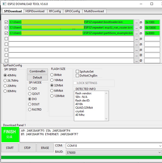
As an alternative you might use Espressif's Flash Download Tools with the parameters given in the figure below (thanks to mahesh2000), update the filenames accordingly:
The following are the steps required to compile this project:
-
Download and setup the ESP-IDF.
-
In the project directory run
make menuconfig(oridf.py menuconfigfor cmake).- *Component config -> LWIP > [x] Enable copy between Layer2 and Layer3 packets.
- *Component config -> LWIP > [x] Enable IP forwarding.
- *Component config -> LWIP > [x] Enable NAT (new/experimental).
-
Build the project and flash it to the ESP32.
A detailed instruction on how to build, configure and flash a ESP-IDF project can also be found the official ESP-IDF guide.
The following are the steps required to compile this project:
- Download Visual Studio Code, and the Platform IO extension.
- In Platformio, install the ESP-IDF framework.
- Build the project and flash it to the ESP32.
For automated building across multiple ESP32 targets with esp-idf, use the provided build scripts:
./build_all_targets.shBy default, the DNS server distributed to AP clients via DHCP is automatically learned from the upstream WiFi connection. Before the first successful STA connection, 1.1.1.1 is used as a fallback.
You can override this with a custom DNS server that is always used regardless of the upstream:
Web Interface: On the /config page, set the "DNS Server" field in Access Point Settings (leave empty for automatic/upstream DNS).
Serial Console:
set_ap_dns 1.1.1.1         # Use Cloudflare DNS
set_ap_dns 8.8.8.8         # Use Google DNS
set_ap_dns ""              # Clear custom DNS (use upstream, default)
The show config command displays the current DNS setting under AP Settings. Changes require a restart to take effect.
All tests used IPv4 and the TCP protocol.
| Board | Tools | Optimization | CPU Frequency | Throughput | Power |
|---|---|---|---|---|---|
ESP32D0WDQ6 |
iperf3 |
0g |
240MHz |
16.0 MBits/s |
1.6 W |
ESP32D0WDQ6 |
iperf3 |
0s |
240MHz |
10.0 MBits/s |
1.8 W |
ESP32D0WDQ6 |
iperf3 |
0g |
160MHz |
15.2 MBits/s |
1.4 W |
ESP32D0WDQ6 |
iperf3 |
0s |
160MHz |
14.1 MBits/s |
1.5 W |