
Hello friends I have made this mini cool looking machine for winding cooper wires.
I have used one numbers of DVD stepper mechanism extracted from old DVD drive of computer
and used one DC motor which is connected via rubber band to the shaft of coiler.
when this DC MOTOR run the coiler will rotate and copper wire start winding on it.

Not all CD/DVD ROM drives have steppers. Sometimes you will find these also under the term "SLED engine". What did I learn from this:
In addition to the current-carrying typical cables, broadband cables are also there to conduct signals and close circuits. Since these are also soldered to components or the PCB, do not just remove it.
Before you start get an overview of what you are actually looking for
because I had in advance no overview of what comes to me when disassembling the drives.
1/8 inch (3mm)) thick acrylic sheet
3/8 inch (10mm) thick MDF board
7/16 inch (12mm) thick wooden board
1 no. scrap DVD drive
1/8 inch (3mm) shaft
13/16 inch (20mm) steel rod
3/16 inch (5mm) threaded rods
Dupont ribbon cable
1 no. 9V DC motor
1 no. 0.96 OLED display
1 no. rotary encoder
1 no. IR sensor
26 AWG copper wire
Rubber belt
Various 3D printed gears and wool spools, etc
3 no. 693 zz ball bearings
2 no. NEMA 17 stepper motor
1 no. custom PCB board
2 no. A4988 stepper driver
1 no. Arduino Nano
1 no. L293D 16-pin IC stepper motor driver controller
M6 X 40 bolts
Various bolts and nuts and acorn cap nuts.
Right, now to get on with the build. Hold on tight, there is a lot to get through.
The basic concept of the machine is to create a smaller spool of copper wire from a larger one automatically. A rotary dial is used to select the number of turns of the wire you want, which displays on the OLED display.
Once set, the machine gets to work in short order.
The first step is to dismantle that old DVD drive you've managed to salvage. You are after the DVD laser head assembly inside.

With that piece isolated, strip and solder the stepper motor terminals to the appropriate contacts on the salvaging DVD player's optical laser head's motor. This will vary depending on the design of the DVD player in question.

Strip off the part you don't need (basically the optical pickup) and make room for the wire guider you will build later. Watch the video for more details on this part.
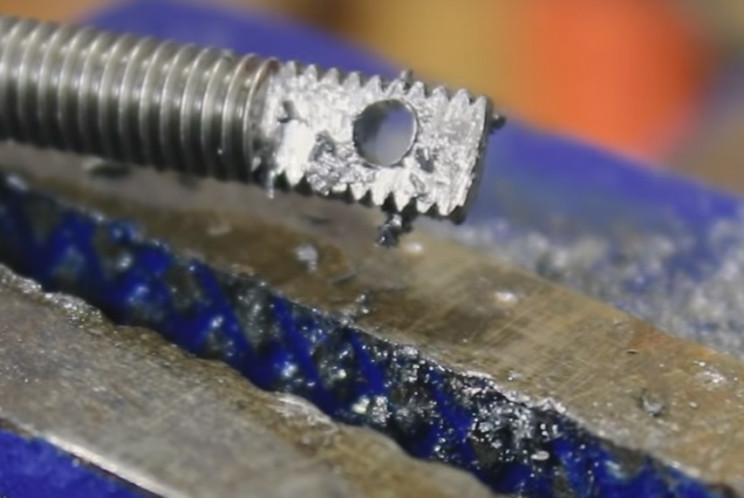
Next up, take the bolt and file flat the topmost part of two opposite sides. This will be used to make the wire guider later on.

Then drill a hole in the center to guide the copper wire between the spools. Bevel the hole, if required.

Now insert the wire guider into the middle of the former DVD laser head assembly. Use a bolt to secure it into place.

Next, take some random plastic pieces, or 3D print them to design. Make, or include in the design, an off-center 5/16 inch (8mm) hole. It will need to be deep enough to hold three 693 ZZ bearings when complete.
Drill and tap one of the sides too, as shown in the video. You will need two identical pieces later. If required, cut down to the final shape.
Again watch the video for more detailed instructions on this section as it will depend on what you get your hands on.
Insert 3 no. ball bearings into the hole.

Test it by Inserting the 1/8 inch (3mm) shaft through the eyes of the ball bearings. This will hold the bobbin for the copper wire later on.
Now take the 13/16 inch (20 mm) aluminum rod. We are now going to machine the pully and bobbin gripper parts of the machine.
Secure into a vice, and drill holes into it as shown in the video, This make take some trial and error. They will need to be M3 size, and tapped, and will be used for the locking nuts.

Machine into shape, as shown in the video. DrilL A 1/8 inch (3mm) hole into the end to fit on the 1/8 inch (3mm) shaft used earlier. Further machine and part-off the finished piece, as shown in the video.
You will also need to make a pulley piece to hold the rubber band. This will be used to turn the bobbin using the DC motor later.

Now assemble the gripper and pulley assembly. Now scavenge some more pieces from the DVD player to built a holder for the DC motor. The process, and dimensions, will vary depending on the DVD player design.
Watch the video for more details on this stage.
Attach the motor assembly to the DVD laser head assembly frame as shown in the video. Also, attach the bobbin gripper assembly in a similar fashion.
Now take the M5 threaded rods. These will be used to make the legs to hold the assembly in place.


Next, we will make the display and knob mounting. Take the acrylic sheet and cut to size, as shown in the video.
Drill holes and cut in notches as also shown in the video. You may want to mock this up before committing to cutting the acrylic sheet.
Heat and bend it to the desired angle.
Now take the IR sensor. This will be used to count the number of turns of the bobbin.
Create a suitably sized, and shaped, mounting for it, and attached the appropriate place on the ex-DVD player's main assembly.


L293D = 2 pieces
LM7809 = 1 piece
LM7805 = 1 piece
10.1uF electrolytic = 1 piece
1N5408 = 1 piece
1N4007 = 1 piece
led = 1 piece
resistance of at least 470 Ohm = 1 piece
Arduino Nano = 1 piece
Oled display = 1 piece
Encoder = 1 piece
A4988 controller = 2 pieces
socket 8 + 8 = 1 piece
PCB female pin header connectors
screw connectors for printed circuit boards
I have designe a PCB which is multipurpose and order it from JLCPCB
Making such projects without PCB is night mare yes trust me you cannot get wanted result and professional touch in your project if you ignore PCB So some days back I have developed my Multipurpose PCB. This PCB is used to build wide range of arduino projects
I have ordered PCB from JLCPCB
This is the link of PCB editabl file
If you seriously need quality PCB quickly in your hand then you must have to try JLCPCB PCB manufacturing service. They have Special offer of $2 for 1-4 Layer PCBs, free SMT assembly monthly. If new user signup today from this link JLCPCB you will get 30$ coupon from JLCPCB.

#include <Wire.h>
#include "SSD1306Ascii.h"
#include "SSD1306AsciiWire.h"
#define I2C_ADDRESS 0x3C
#define RST_PIN -1
SSD1306AsciiWire oled;

#define EN 5
#define M1 3
#define M2 4
#define OUTA 9
#define OUTB 8
#define SW 6

int state = 0;
int statea = 0;
int Astate = 0;
int Alaststate = 0;
int count = 0;
int PWM=200;
int startpos =120;
int minpos=140;
int maxpos =178;
int pos;
int pause = 20;
int k;
int encoder_pin = 2; // pulse output from the module

int pulses;
int x ;


void counter()
{
//Update count
pulses++;
}

void setup() {
Wire.begin();
Wire.setClock(400000L);
//Serial.begin(9600);
#if RST_PIN >= 0
oled.begin(&Adafruit128x64, I2C_ADDRESS, RST_PIN);
#else // RST_PIN >= 0
oled.begin(&Adafruit128x64, I2C_ADDRESS);
#endif // RST_PIN >= 0

oled.setFont(Adafruit5x7);
oled.clear();
pinMode(SW, INPUT_PULLUP);
pinMode(OUTA, INPUT);
pinMode(OUTB, INPUT);
pinMode(EN, OUTPUT);
pinMode(M1, OUTPUT);
pinMode(M2, OUTPUT);
Alaststate = digitalRead(OUTA);
Serial.begin(9600);

pinMode(encoder_pin, INPUT);
//Interrupt 0 is digital pin 2
//Triggers on Falling Edge (change from HIGH to LOW)
attachInterrupt(0, counter, RISING);
// Initialize
pulses = 0;
}


void loop() {
motstop();
oled.set2X();
oled.setCursor(0, 0);
oled.println(" TURNS");
oled.set1X();
oled.setCursor(0, 13);
oled.println("---------------------");
Astate = digitalRead(OUTA);
if (Astate != Alaststate){
// If the outputB state is different to the outputA state, that means the encoder is rotating clockwise
if (digitalRead(OUTB) != Astate) {
count ++;
} else {
count ++;
}
// Serial.print("Position: ");
// Serial.println(count);
oled.set2X();
oled.setCursor(40,4);
oled.println( count*10);
}

if(!digitalRead(SW)){
Serial.println("START");
motrun();

}


}


void motrun(){
digitalWrite(EN, HIGH);
digitalWrite(M1,HIGH);
digitalWrite(M2,LOW);
}

void motstop(){
digitalWrite(EN, LOW);
digitalWrite(M1,LOW);
digitalWrite(M2,LOW);
}