Collaborators: Daniel Shenkelman, Eli Levenshus, Joe Li
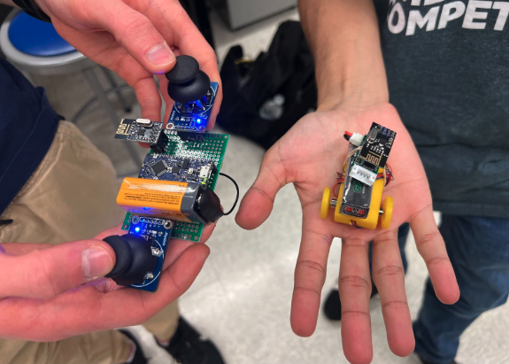
The goal of this project is to create a tiny, controllable robot with a custom RF remote control. It involves having two independent Arduinos talking to each other over radio frequencies. The remote control will have an Arduino Nano that takes input from two joystick modules and an Arduino nRF24L01 to transmit a signal to a robot. The robot then uses this corresponding signal to control two driver motors, which causes the robot to move.
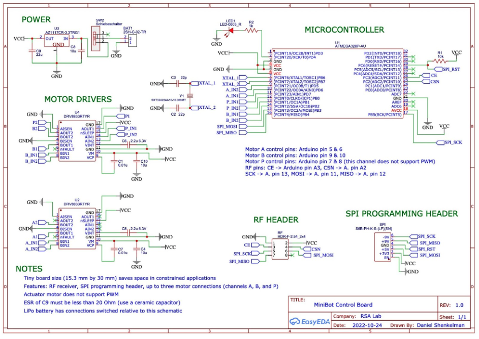
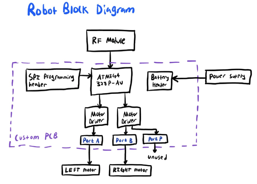
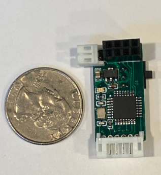
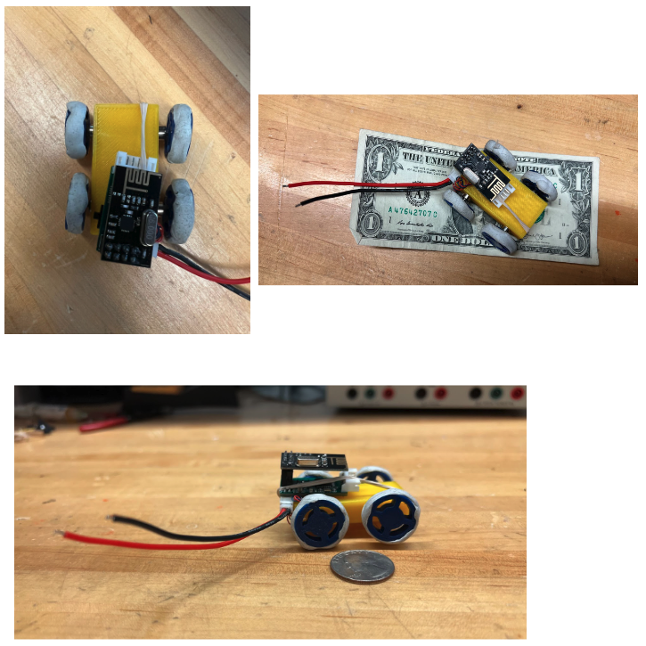
This project aims to make the robot as small as possible. A custom PCB was created and designed from scratch with as small of a form factor as possible to accomplish this. This PCB utilizes an ATMEGA328P-AU microcontroller, two DRV8833 DC motor drivers, and can control three tiny DC motors. This PCB design also includes an RF header, a SPI Programming Header, and is powered by a 3.7V LiPo battery. The tiny board size is 15.3 mm by 30 mm, which saves space in constrained applications.
-
Set up motors with motor driver breakout boards, ensuring they can carry adequate load
-
Set up the transmitter and receiver modules on a breadboard to ensure data can send
-
Design, order, and assemble receiver PCB based on the breadboard design
-
Flash bootloader onto receiver PCB
-
Program the receiver PCB and ensure its functionality
-
Build a small chassis to attach the motors to the PCB, and add 3d-printed wheels.
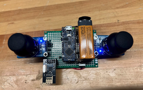
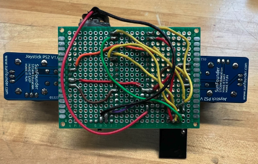
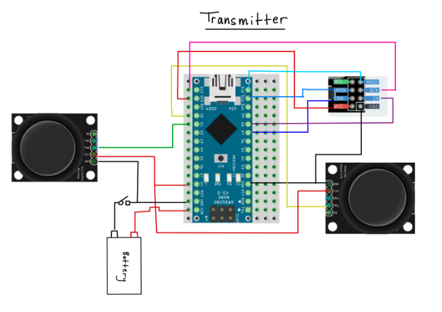
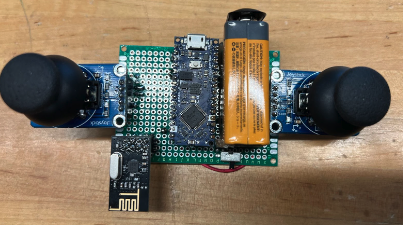
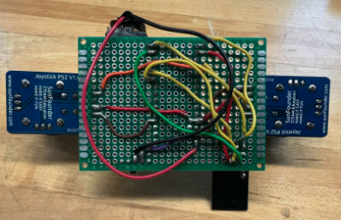
One of the sensors built and used in this project is a custom RF remote control that controls the movement of the MiniBot. The main components of the remote control are an Arduino Nano Every, an Arduino nRF24L01 (wireless RF Transceiver Module), two Analog Joysticks, and powered by a 9-volt battery. The remote control transmits motor values mapped from the joystick position. We created Arduino programs that use the nRF24L01 radio frequency transceiver and SPI for serial communication.
The other sensors used are joysticks, which take data from two potentiometers ranging from -512 to 512 for a total analog range of 0-1023. The joystick's position is sampled by the Arduino on the transmission board, then scaled and sent to the Arduino on the Minibot.
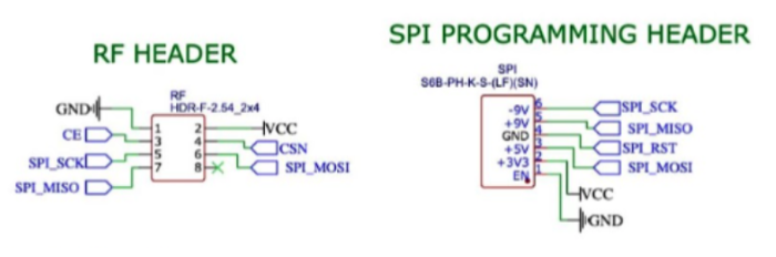
There is a corresponding RF Receiver on the MiniBot Control Board (custom PCB) with an RF Header and SPI Programming Header. The RF Module is connected specifically to the ATMEGA328P-AU. The Arduino Receiver code was also created to receive transmitted data and control two motors.
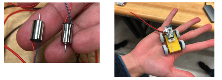
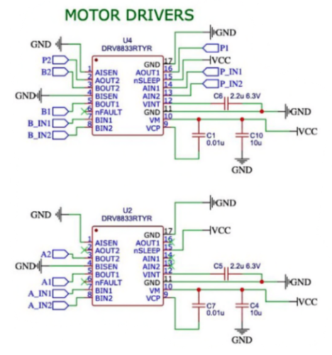
This project utilized two Adafruit DRV8833 DC Motor Driver Breakout Boards. This controls/spins the two cordless micro DC motors connected to the wheels of the MiniBot. A chassis was designed and 3D-printed to connect the motor shafts to the wheels while keeping all wiring in place. The PCB was then placed on top of the chassis to ensure proper connections to the motor drivers. The custom PCB contains two motor drivers, one controlling the back left side motor and left wheel, and the other controlling the back right side motor and right wheel.
created by Daniel Shenkelman