3. The Electrical
Within this pinball machine are two separate electrical systems working in tandem: a low voltage (5v) Ardunio system and a high voltage (50v) solenoid system. I would like to reiterate that extra care should be taken when working on these two systems to make sure that they do not interact except for where intended. Unregulated 50v is enough to instantly destroy your Arduino and any of the low voltage components attached to it. All solder joints should be covered in electrical tape as an extra precaution and you should test the system after every step. This ensures that you won't damage everything all at once should something happen and that you will be able to better tell where an issue is should one arise. I also advise not working in the cabinet while it is powered. It is very easy to forget yourself and touch live voltage so it's always safer to just unplug the machine before doing anything.
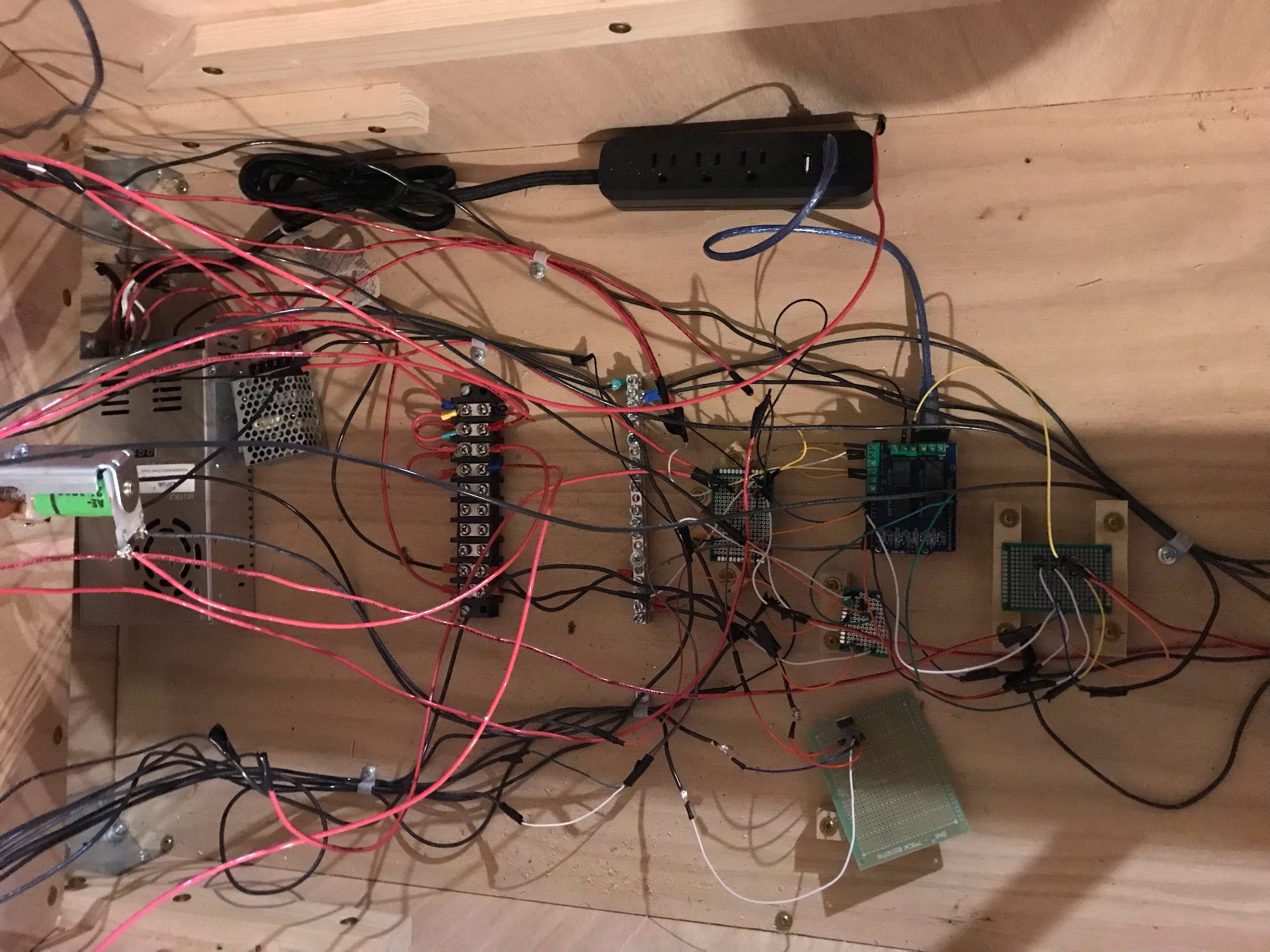
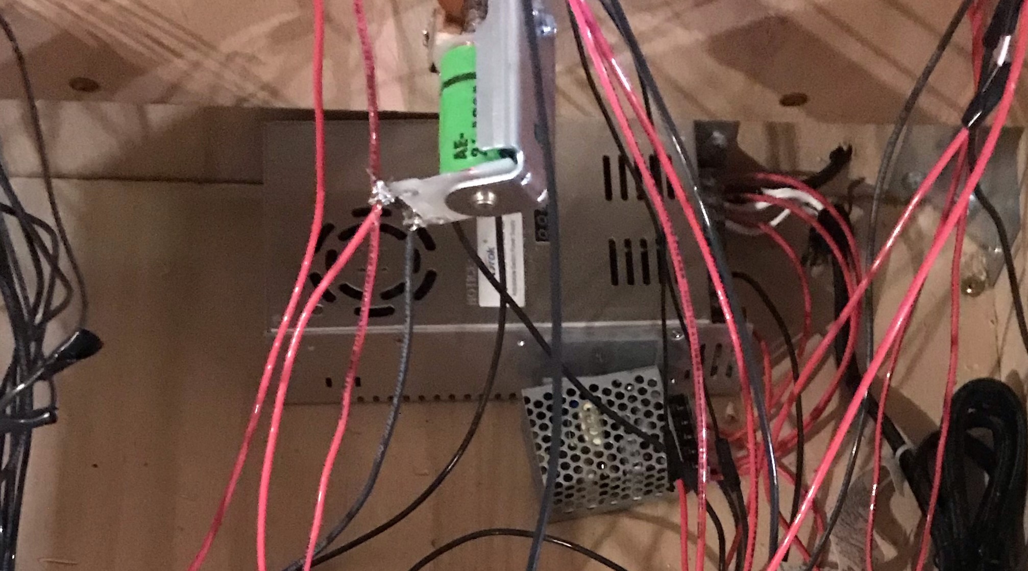
The first component of this system is of course your power sources. The 50v AC-DC is for powering the solenoids and the 12v AC-DC is relayed through the Arduino for controlling the bumpers (more on that later). To use these power sources, cut the end off of a standard computer power cord and tie the exposed wires to the appropriately marked terminals on the power sources. Double check these connections before plugging the system in for the first time in order to avoid damaging your power sources. As you may have noticed, the Arduino requires a 5v USB power supply that is currently unaccounted for. An easy solution to this is get a power strip with a USB port built into. The end of this can be cut just like the other power cord and tied into the same terminals as the power supplies. Then you can plug the Arduino power cord into this to power it.
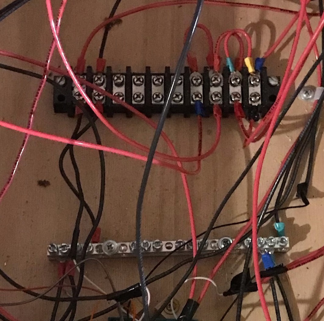
This step is important for the organization of your system. The power distribution block and the grounding block are useful components as they enable you to add and remove items from the system without having to solder and unsolder. As you can see in the image below, power from the 50v power source should be run to one end terminal of the power block while the 12v power should be run to the other. Each of the individual terminal is not connected the others so the 12v and 50v are still kept separate. The ground lines from both power sources should be tied into the grounding bar and since there is no voltage at ground, separation does not matter. As you add in new components for power, you will need to jump a wire from one powered terminal to the next to provide power. All ground lines can be screwed directly into the terminals on the ground bar.
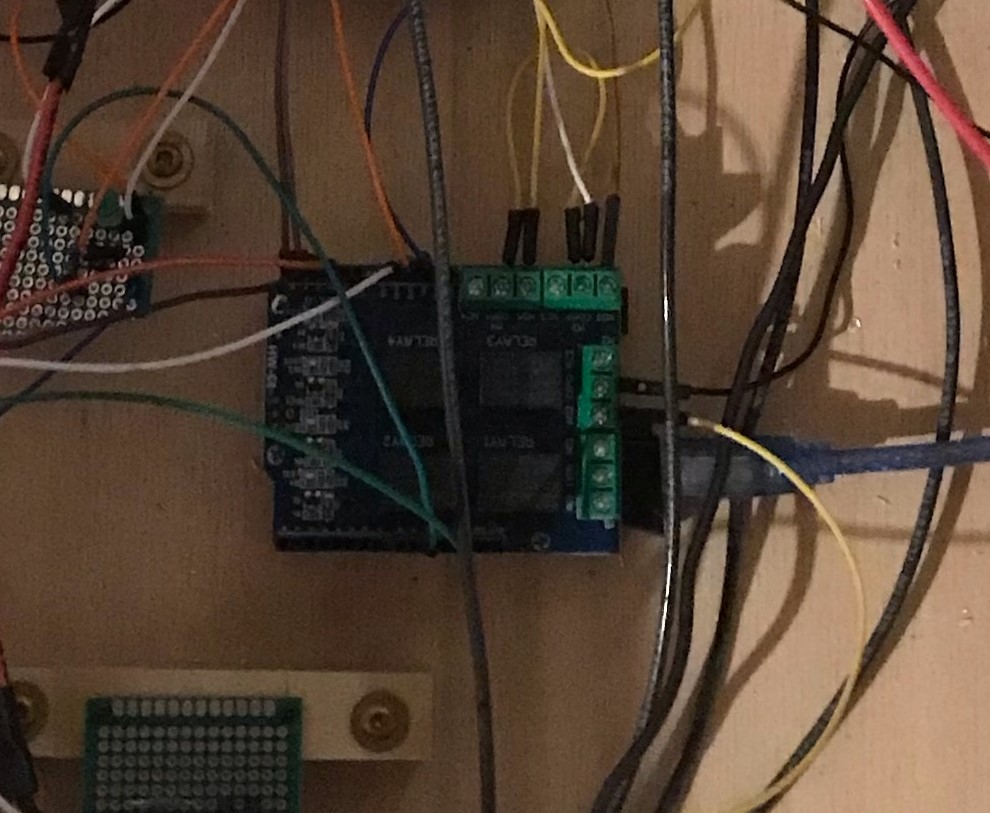
At this point we can install the brains of the pinball machine nearby the power and ground blocks. The Arduino should have the relay shield attached over top of it. The relay shield will allow the Arduino to control the 12v power supply. From here on out, refer to the file "pinballControl.ino" for all Arduino pin assignments. An important job of this Arduino will be to interpret several inputs to determine if a switch has been hit. For this reason, for any of the lines that are meant to be read by the Arduino, they must first be wired with a pull down resistor to ensure that no erroneous signals are received.
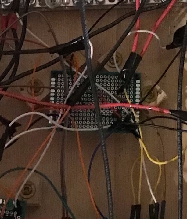
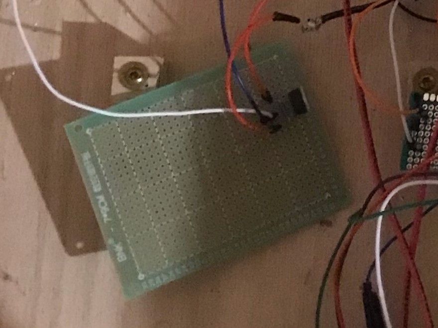
For this project you will need to use many different modules with the Arduino. All of these will require 5v power, but the Arduino only has one 5v pin. To remedy this, you will need to run that 5v to a pcb into which you will solder all of your components that require 5v. You can use the same pcb to do the same thing for the Arduino's ground pin. Once you are done with this project, the pcb should be secured down to keep it from contacting the high voltage system but only after you are done. If you secure it down before, you will not be able to get underneath it to solder.
The bumper consist of two parts, the leaf switch and the coil. The leaf switch has 5v from the Arduino on one side of it and a connection to the Arduino on the other end of it. If the leaf switch is hit, then it completes the circuit and sends 5v to the Arduino. The solenoid has two contacts. The rightmost contact should be connected to the 50v on the power block. The leftmost contact connects to a simple MOSFET circuit that I'll explain in the next step. You should also connect a diode reverse biased from the leftmost contact to the rightmost contact.
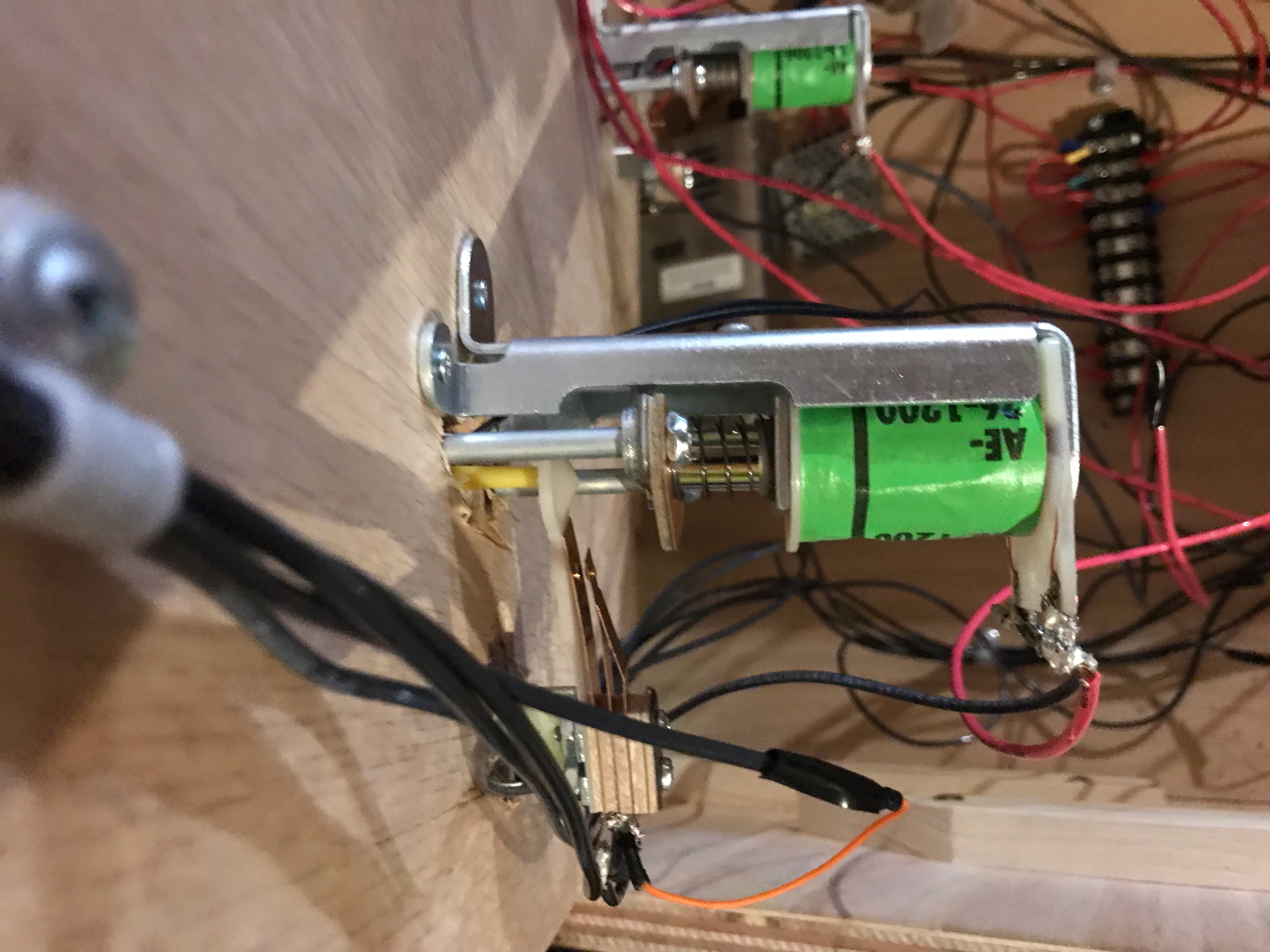
This MOSFET circuit is what enable the Arduino to control the pop bumpers. Connect 12v from the power block to the com on a relay of the relay shield. Connect the left pin of the MOSFET to the NOC terminal of the relay. Connect the wires from the leftmost terminals of the bumpers to the center pin of the MOSFET. Lastly, connect the right most pin of the MOSFET to the ground bar. Now, if the Arduino detects a signal from the leaf switch, it will turn on the relay which will send 12v to the MOSFET which will turn it on and fire the bumpers.
As you can see in the picture below, the flippers are wired a bit differently. If you would like to know the reason, I explain the operation of pinball flippers in my general pinball section. For the purposes of this project, we just need to know that power gets connected to the right most contact, ground gets connected to the leftmost contact, and then both the middle and leftmost contact get connected to one side of the leaf switch (not the same side though).
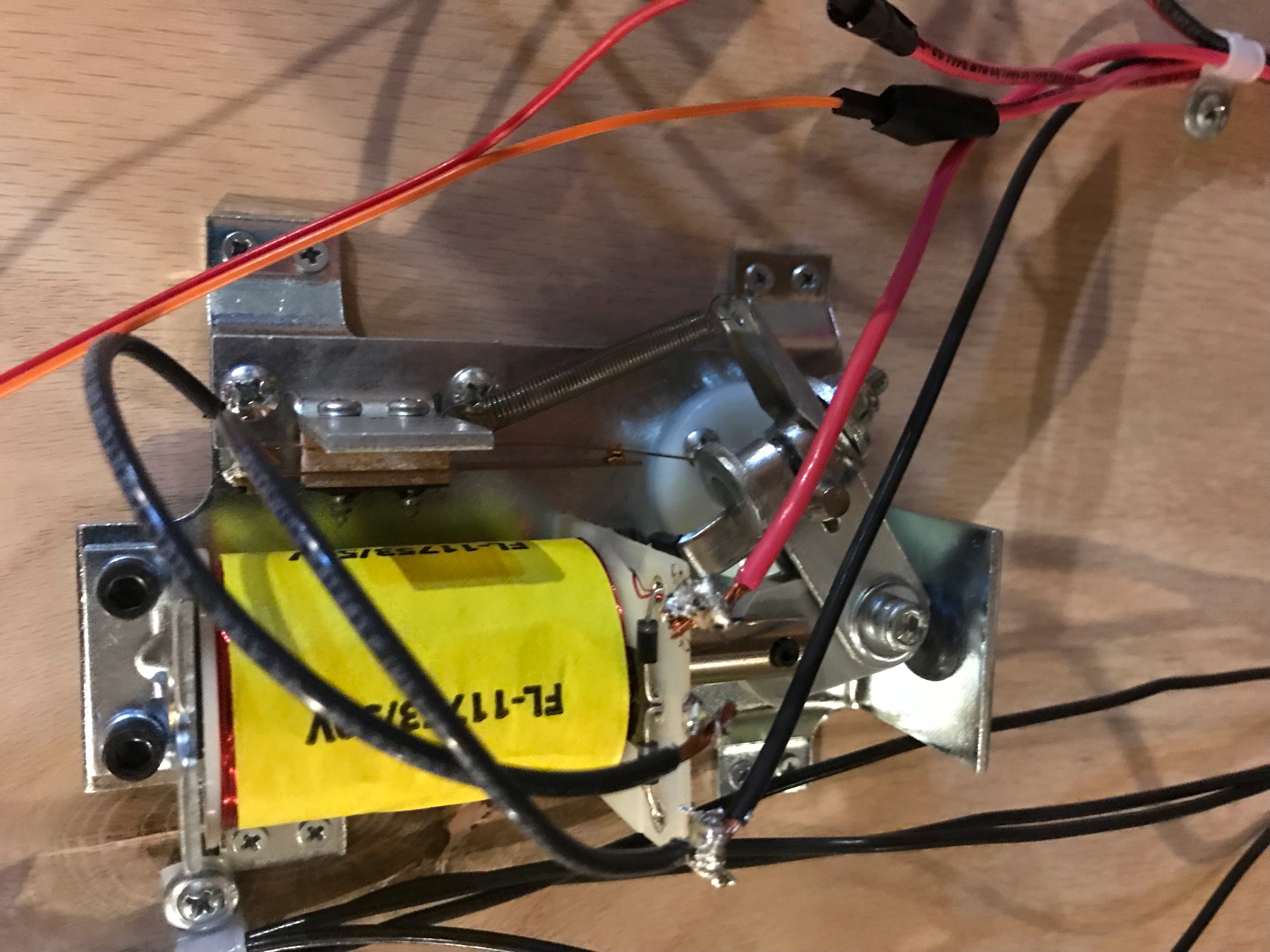
It might seem counterintuitive but the flipper controls are not tied to the Arduino at all. The flipper has only electromechanical controls. The ground line from the flipper gets connected to the COM of the button (left flipper to left button and right flipper to the right button). The NOC of the button connects to ground. Now the circuit is open until the switch is hit at which time the flipper will fire.
Each pop bumper as a single light in the center of it. These can easily be turned on and off using the relay shield. Run one leg of each light to the NOC of a relay terminal and then run 12v to the COM of the terminal. Run the other leg of each light to ground. Now if the relay is turned on the light will come on.
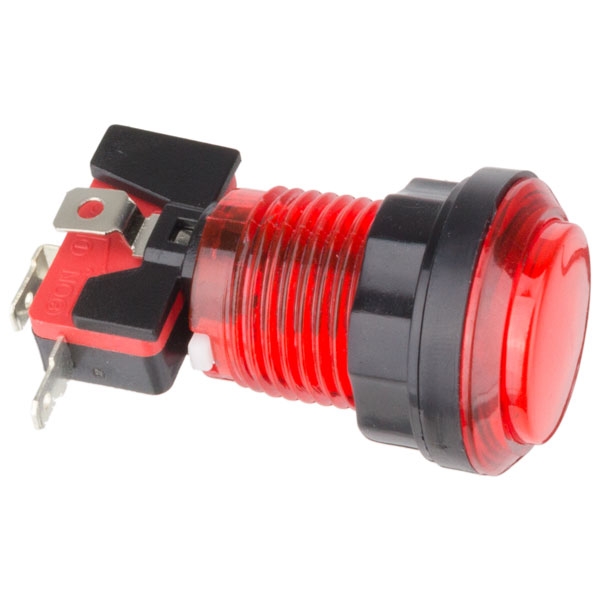
The only components left interface with the Arduino very similarly. The I2C LCD has specific analog ports it connects to which can be found online. The start button is connected like a leaf switch, with 5v on one end and the other end connected to a pull down resistor and a digital port on the Arduino. Lastly, there are two pressure sensors, one for the ramp and one for the ball return. These return a varying voltage level which means that they get attached to an analog pin so that the Arduino can differentiate the voltage level.
With the completion of step 10 you should have a working pinball machine. There may be some slight tweaking required but if you've done you due diligence and testing with every step, then you should have only minor issues if any.