Replication Studies
Replication studies are a core component of AntennaCAT! This page is an overview of the replication studies included in the current version of the AntennaCAT software, their sources, and some general information about the topologies. When possible, the default values are set to the optimized or experimental solutions from the source publication.
Table of Contents
Three of the replication studies compliment the internal calculator.
| Parameter | Default Value | Usage |
|---|---|---|
| Feed Method | microstrip | Feed method of the patch. microstrip or probe |
| Conductor Material | copper | Conductor material selected from internal library |
| Substrate Material | FR4_epoxy | Substrate material selected from internal library |
| Substrate Height | 1.6 mm | Physical height or thickness of substrate |
| Substrate Length | 80 mm | Total substrate length |
| Substrate Width | 100 mm | Total substrate width |
| Dielectric Constant | 4.4 | Updated by Substrate Material drop down menu, not used for calculation |
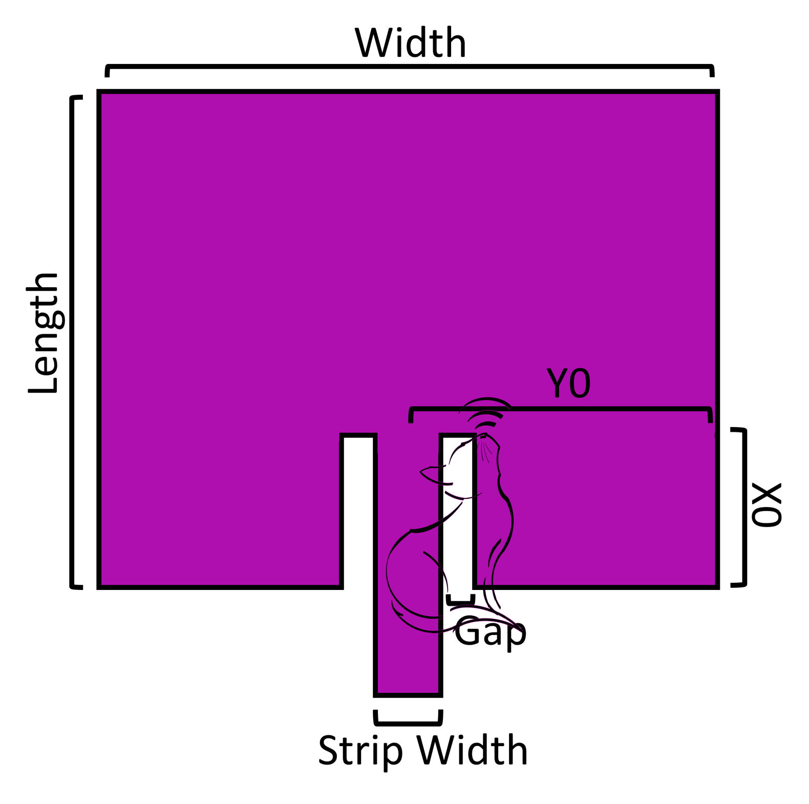
| Length | 29.44 mm | Length of patch conductor |
| Width | 38.04 mm | Width of patch conductor |
| X0 | 11.32 mm | Feed inset, length dimension |
| Y0 | 19.02 mm | Feed inset, width dimension |
| Gap | 1 mm | If microstrip, channel between strip and patch |
| Strip Width | 3.06 mm | If microstrip, width of feed strip |

Publication Reference: This design is based on those mentioned : C. A. Balanis, Antenna Theory: Analysis and Design. Hoboken, NJ: Wiley, 2016.

| Parameter | Default Value | Usage |
|---|---|---|
| Conductor Material | copper | Conductor material selected from internal library |
| Total Length | 60 mm | Total length of the dipole |
| Wire Radius | 1 mm | Radius of the wire |
| Feed Gap | 5 mm | The space between the two halves of the dipole |

Publication Reference: This design is based on those mentioned : C. A. Balanis, Antenna Theory: Analysis and Design. Hoboken, NJ: Wiley, 2016.

| Parameter | Default Value | Usage |
|---|---|---|
| Conductor Material | copper | Conductor material selected from internal library |
| Wire Radius | .15 mm | The radius of the wire |
| Ground plane Radius | 75 mm | The radius of the ground plane. Conductive material only, no substrate |
| Feed Gap | 1.5 mm | The space between the wire and the ground plane |

Publication Reference: This design is based on those mentioned : C. A. Balanis, Antenna Theory: Analysis and Design. Hoboken, NJ: Wiley, 2016.

| Parameter | Default Value | Usage |
|---|---|---|
| Conductor Material | copper | Conductor material selected from internal library |
| Distance from Ground plane | 15 mm | length of the feed, distance between E and ground plane. No substrate |
| Ground plane Length | 125 mm | Total ground plane length |
| Ground plane Width | 125 mm | Total ground plane width |
| Length | 30 mm | Primary length of conductor |
| Width | 30 mm | Primary width of conductor |
| X | 0 mm | offset of feed from origin in X direction (Length direction) |
| Ps | 7.5 mm | distance var |
| Ls | 20 mm | distance var |
| Ws | 5 mm | distance var |

Publication Reference:
- A. Z. Hood and E. Topsakal, "Particle swarm optimization for dual-band implantable antennas," 2007 IEEE Antennas and Propagation Society International Symposium, Honolulu, HI, USA, 2007, pp. 3209-3212, doi: 10.1109/APS.2007.4396219.
- N. Jin and Y. Rahmat-Samii, "Parallel particle swarm optimization and finite- difference time-domain (PSO/FDTD) algorithm for multiband and wide-band patch antenna designs," in IEEE Transactions on Antennas and Propagation, vol. 53, no. 11, pp. 3459-3468, Nov. 2005, doi: 10.1109/TAP.2005.858842.
| Parameter | Default Value | Usage |
|---|---|---|
| Conductor Material | copper | Conductor material selected from internal library |
| Substrate Material | FR4_epoxy | Substrate material selected from internal library |
| Substrate Height | 1.6 mm | Physical height or thickness of substrate |
| Substrate Length | 125 mm | Total substrate length |
| Substrate Width | 150 mm | Total substrate width |
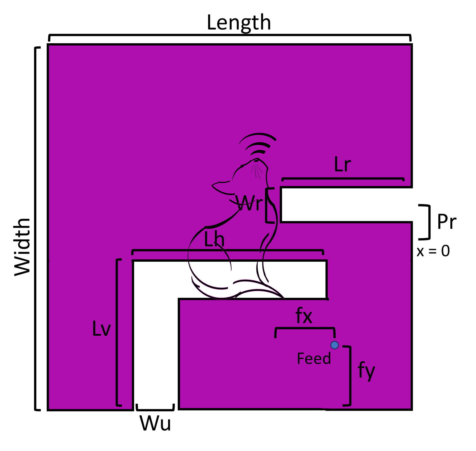
| Length | 60.45 mm | Primary length of conductor |
| Width | 65.96 mm | Primary width of conductor |
| fx | 22.43 mm | feed X |
| fy | 7.69 mm | feed Y |
| Lr | 6.82 mm | distance var |
| Lv | 22.85 mm | distance var |
| Wr | 6.45 mm | distance var |
| Lh | 54.1 mm | distance var |
| Pr | -5.21 mm | distance var |
| Wu | 7.04 mm | distance var |
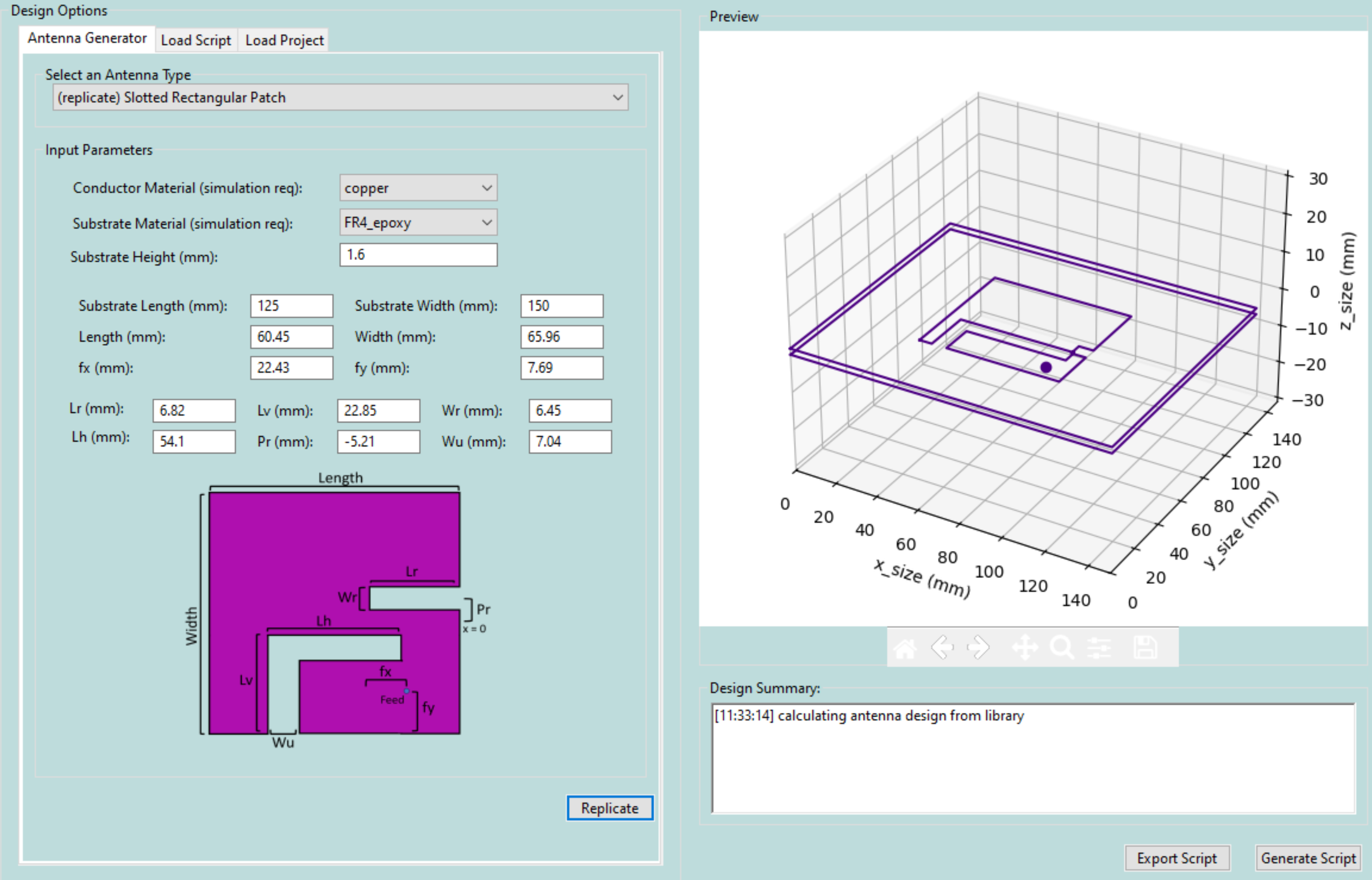
Publication Reference:
- A. Aldhafeeri and Y. Rahmat-Samii, "Brain Storm Optimization for Electromagnetic Applications: Continuous and Discrete," in IEEE Transactions on Antennas and Propagation, vol. 67, no. 4, pp. 2710-2722, April 2019, doi: 10.1109/TAP.2019.2894318.

| Parameter | Default Value | Usage |
|---|---|---|
| Conductor Material | copper | Conductor material selected from internal library |
| Substrate Material | FR4_epoxy | Substrate material selected from internal library |
| Substrate Height | 1.6 mm | Physical height or thickness of substrate |
| Lsub | 22.5 mm | Total substrate length |
| Wsub | 22.5 mm | Total substrate width |
| Lp | 22.0 mm | distance var |
| Wp | 17.75 mm | distance var |
| Ps1 | -7.0 mm | distance var |
| Ls1 | 19.1 mm | distance var |
| Ws1 | 2.7 mm | distance var |
| Px | 0.2 mm | distance var |
| Ps2 | -3.9 mm | distance var |
| Ls2 | 20.1 mm | distance var |
| Ws2 | 0.5 mm | distance var |
| Py | 0.2 mm | distance var |
| Ps3 | 0.5 mm | distance var |
| Ls3 | 18.0 mm | distance var |
| Ws3 | 2.0 mm | distance var |
| Fy | 0.1 mm | distance var |
| Ps4 | 3.5 mm | distance var |
| Ls4 | 17.5 mm | distance var |
| Ws4 | 0.6 mm | distance var |
| Lc | 09.6 mm | distance var |

Publication Reference:
- T. Karacolak, A. Z. Hood and E. Topsakal, "Design of a Dual-Band Implantable Antenna and Development of Skin Mimicking Gels for Continuous Glucose Monitoring," in IEEE Transactions on Microwave Theory and Techniques, vol. 56, no. 4, pp. 1001-1008, April 2008, doi: 10.1109/TMTT.2008.919373.

| Variable | Default Value | Usage |
|---|---|---|
| Conductor Material | copper | Conductor material selected from internal library |
| Substrate Material | FR4_epoxy | Substrate material selected from internal library |
| Substrate Height | 1.6 mm | Physical height or thickness of substrate |
| Substrate Length | 100 mm | Total substrate length |
| Substrate Width | 150 mm | Total substrate width |
| Feed Width | 3 mm | Width of the feed strip |
| Gap Distance | 2.582 mm | Gap between the two halves of bowtie |
| Width | 46.875 mm | Width of one half of conductor (one triangle) |
| Length | 31.25 mm | Length of one half conductor (one triangle) |

Publication Reference: This design is based on those mentioned : C. A. Balanis, Antenna Theory: Analysis and Design. Hoboken, NJ: Wiley, 2016.

| Variable | Default Value | Usage |
|---|---|---|
| Conductor Material | copper | Conductor material selected from internal library |
| Substrate Material | FR4_epoxy | Substrate material selected from internal library |
| Substrate Height | 1.6 mm | Physical height or thickness of substrate |
| Substrate Length | 150 mm | Total substrate length, centered at origin |
| Substrate Width | 150 mm | Total substrate width, centered at origin |
| Initial Width | 10 mm | The width of the first segment from the feed |
| Initial Length | 10 mm | The length of the first segment from the feed |
| Strip Width | 2 mm | strip width of the arms of the spiral |
| Spacing | 4.5 mm | space between the arms |
| Feed X | 0 mm | offset from origin |
| Feed Y | 0 mm | offset from origin |

Publication Reference: [1] This initial design is based off of the simple version of the spiral at https://www.mathworks.com/help/antenna/ref/spiralrectangular.html . Other replicated spirals use more parameters, including the number of turns.

| Variable | Default Value | Usage |
|---|---|---|
| Conductor Material | copper | Conductor material selected from internal library |
| Substrate Material | FR4_epoxy | Substrate material selected from internal library |
| Substrate Height | 1.6 mm | Physical height or thickness of substrate |
| Substrate Length | 50 mm | Total substrate length |
| Substrate Width | 50 mm | Total substrate width |
| Outer Radius | 17.6 mm | Radius of the outside of the outer loop |
| Inner Radius | 2.1 mm | Radius of the outside of the inner part of the keyhole antenna |
| Feed Width | 4 mm | Width of the feed strip for both the inner and outer parts |
| Feed Length | 29.0 mm | Length of the inset of the inner conductor |

Publication Reference:
- U. Hasni and E. Topsakal, "Wearable Antennas for On-Body Motion Detection," 2020 IEEE USNC-CNC-URSI North American Radio Science Meeting (Joint with AP-S Symposium), Montreal, QC, Canada, 2020, pp. 1-2, doi: 10.23919/USNC/URSI49741.2020.9321663.
- U. Hasni, M. E. Piper, J. Lundquist and E. Topsakal, "Screen-Printed Fabric Antennas for Wearable Applications," in IEEE Open Journal of Antennas and Propagation, vol. 2, pp. 591-598, 2021, doi: 10.1109/OJAP.2021.3070919.

| Variable | Default Value | Usage |
|---|---|---|
| Conductor Material | copper | Conductor material selected from internal library |
| Substrate Material | FR4_epoxy | Substrate material selected from internal library |
| Substrate Height | 1.6 mm | Physical height or thickness of substrate |
| Substrate Length | 50 mm | Total substrate length |
| Substrate Width | 50 mm | Total substrate width |
| Outer Radius | 12 mm | Outer radius of the loop |
| Inner Radius | 10 mm | inner radius of the loop |
| Loop Inset | 15 mm | Length of the feed lines |
| Gap Distance | 1.5 mm | Distance of gap between the feed lines |
| Feed Width | 3 mm | Width of the feed line |

Publication Reference: This design is based on those mentioned : C. A. Balanis, Antenna Theory: Analysis and Design. Hoboken, NJ: Wiley, 2016.
| Variable | Default Value | Usage |
|---|---|---|
| Conductor Material | copper | Conductor material selected from internal library |
| Substrate Material | FR4_epoxy | Substrate material selected from internal library |
| Substrate Height | 1.6 mm | Physical height or thickness of substrate |
| Substrate Length | 50 mm | Total substrate length |
| Substrate Width | 50 mm | Total substrate width |
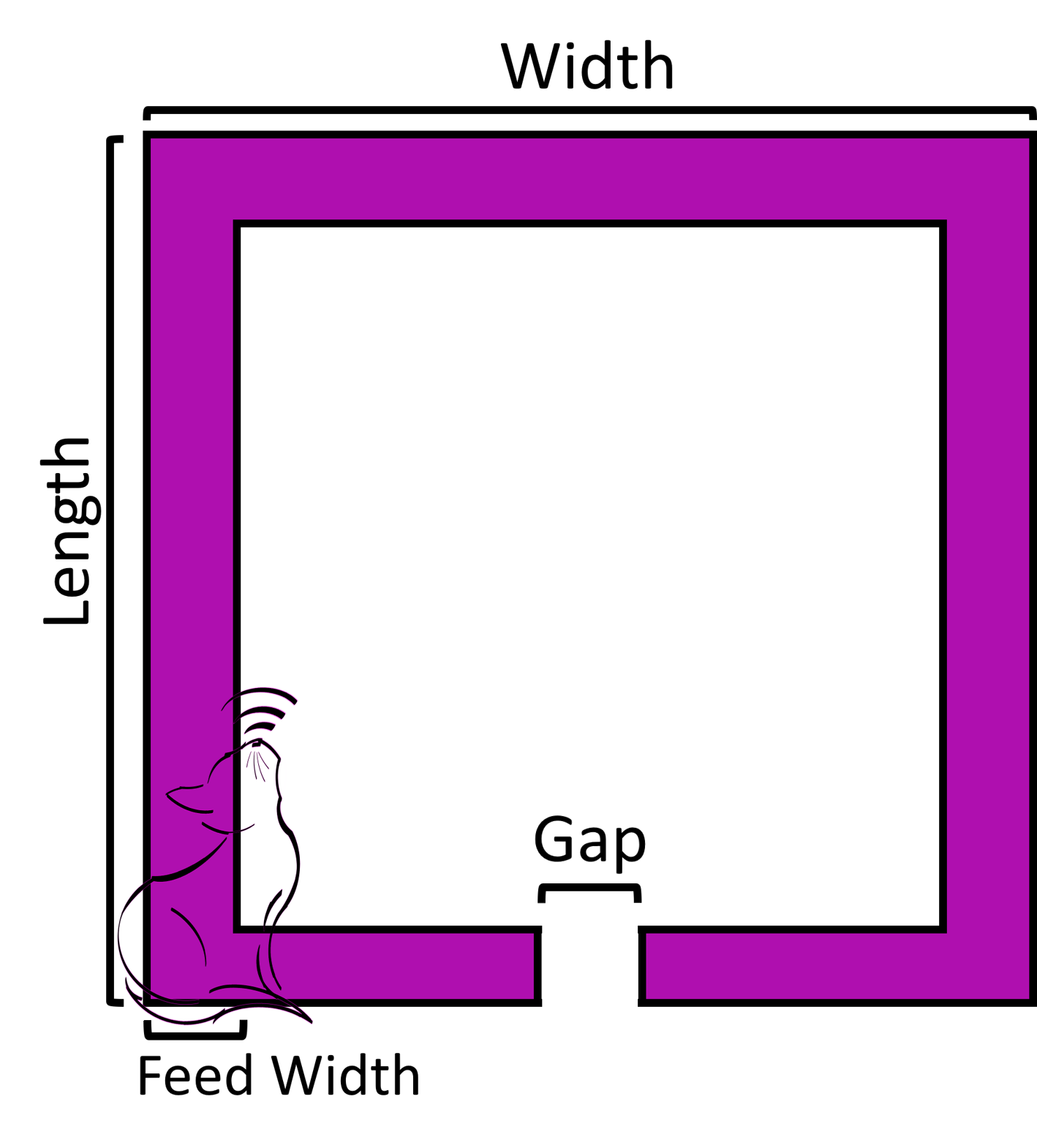
| Length | 15 mm | Primary length of conductor |
| Width | 15 mm | Primary width of conductor |
| Feed Width | 3 mm | Width of the feed strip of the loop |
| Gap Distance | 1.5 mm | Distance of the gap of the feed |

Publication Reference: This design is based on those mentioned : C. A. Balanis, Antenna Theory: Analysis and Design. Hoboken, NJ: Wiley, 2016.
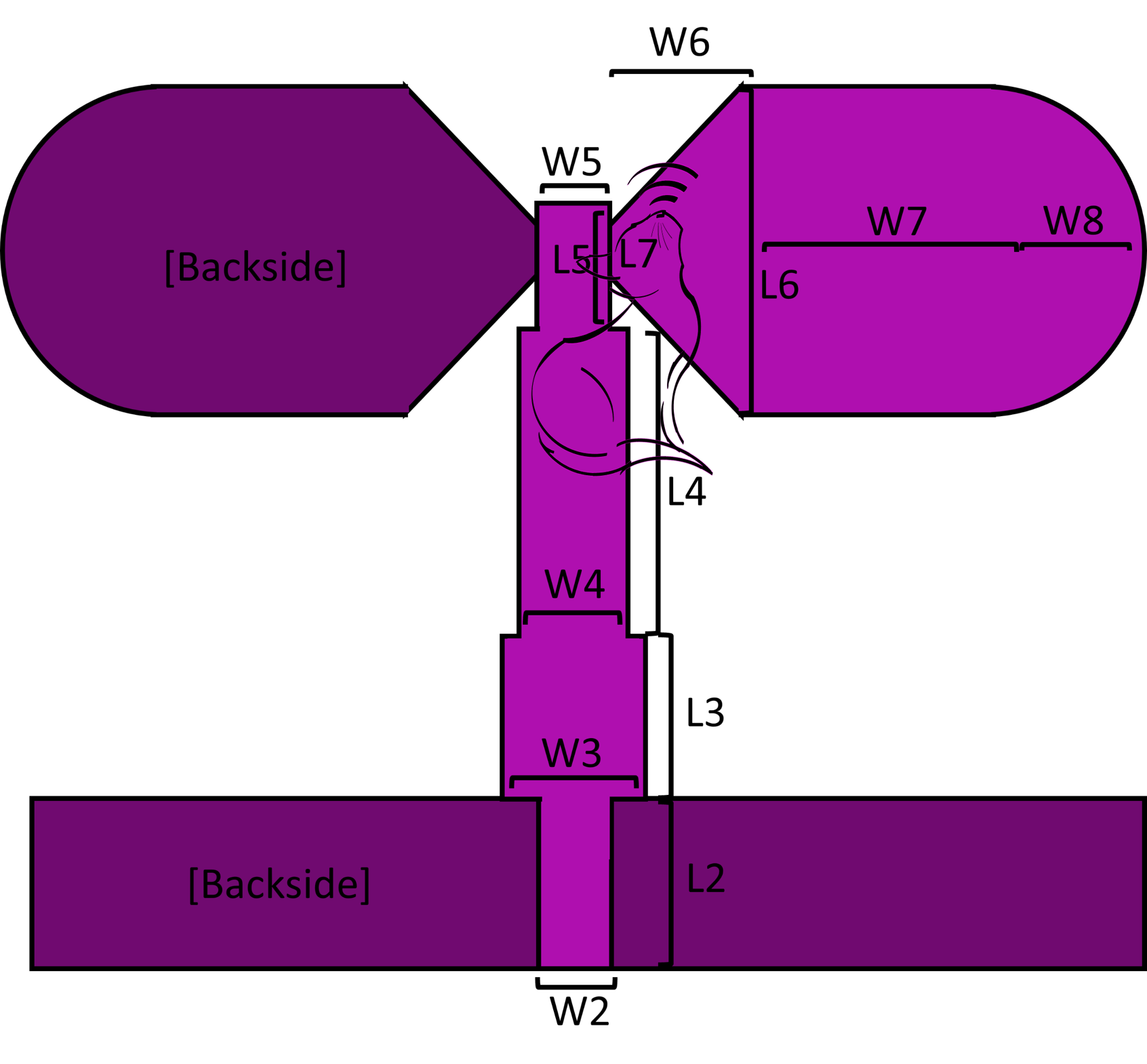
| Parameter | Default Value | Usage |
|---|---|---|
| Conductor Material | copper | Conductor material selected from internal library |
| Substrate Material | FR4_epoxy | Substrate material selected from internal library |
| Substrate Height | 1.27 mm | Physical height or thickness of substrate |
| Substrate Length | 36 mm | Total substrate length |
| Substrate Width | 36 mm | Total substrate width |
| W2 | 1.87 mm | distance var |
| W3 | 2.8 mm | distance var |
| W4 | 2.6 mm | distance var |
| W5 | 1.4 mm | distance var |
| W6 | 2.3 mm | distance var |
| W7 | 9 mm | distance var |
| W8 | 1 mm | distance var |
| L2 | 6 mm | distance var |
| L3 | 4.6 mm | distance var |
| L4 | 11.9 mm | distance var |
| L5 | 3.2 mm | distance var |
| L6 | 12 mm | distance var |
| L7 | 0.8 mm | distance var |

Publication Reference:
- T. Karacolak and E. Topsakal, "A Double-Sided Rounded Bow-Tie Antenna (DSRBA) for UWB Communication," in IEEE Antennas and Wireless Propagation Letters, vol. 5, pp. 446-449, 2006, doi: 10.1109/LAWP.2006.885013.